
Vehicle travel control device

Active Publication Date: 2015-10-15
TOYOTA JIDOSHA KK
View PDF5 Cites 13 Cited by
  • Summary
  • Abstract
  • Description
  • Claims
  • Application Information

AI Technical Summary

Benefits of technology

The invention relates to a running control device for a vehicle that can automatically return to a normal running mode after an inertia running mode. The device uses the gear ratio of the transmission to optimize the responsiveness and acceleration performance of the vehicle. By changing the gear ratio at the time of return to the normal running mode, the device ensures a smooth transition and prevents the user from feeling strangeness during the process. The device also takes into account the engine speed and vehicle speed to determine the gear ratio, ensuring the best performance under different driving conditions.

Problems solved by technology

Therefore, if the engine is in the “stop state”, the engine must be started at the time of return from the inertia running mode and, therefore, the responsiveness until start of generation of a drive force is deteriorated as compared to when the engine is in the “idle state”.
On the other hand, it is newly discovered that, if the gear ratio of the transmission is set on the high vehicle speed side in the case of return from the “idle state” so as to improve the responsiveness at the time of return from the “stop state” in accordance with the return from the “stop state”, an absolute value of the drive force capable of being generated after the return becomes smaller and makes it difficult to acquire desired acceleration, resulting in deterioration in acceleration performance.
Particularly, in the case of the “idle state”, a user expects that the desired drive force is generated because the engine is originally operating and, therefore, a phenomenon of a small drive force at the time of return to the normal running mode tends to give a feeling of strangeness to the user.

Method used


Image

  • Vehicle travel control device
  • Vehicle travel control device
  • Vehicle travel control device

Examples


first example

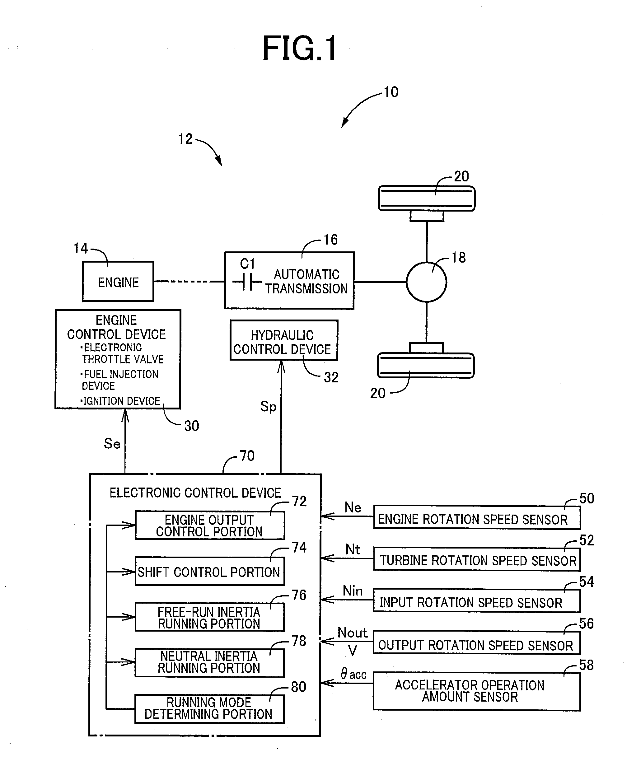
[0030]FIG. 1 is a diagram for explaining a general configuration of a drive device 12 included in a vehicle 10 to which the present invention is applied, and is a diagram for explaining a main portion of a control system for various controls in the vehicle 10. In FIG. 1, the drive device 12 includes an engine 14 and an automatic transmission 16 and the power of the engine 14 acting as a drive force source is transmitted from the automatic transmission 16 via a differential gear device 18 to left and right wheels 20. For example, a damper device and a power transmission device such as a torque converter are disposed between the engine 14 and the automatic transmission 16, and a motor generator acting as a drive force source can also be disposed therebetween.

[0031]The engine 14 includes an engine control device 30 having various pieces of equipment necessary for output control of the engine 14, such as an electronic throttle valve, a fuel injection device, and an ignition device. The ...

second example

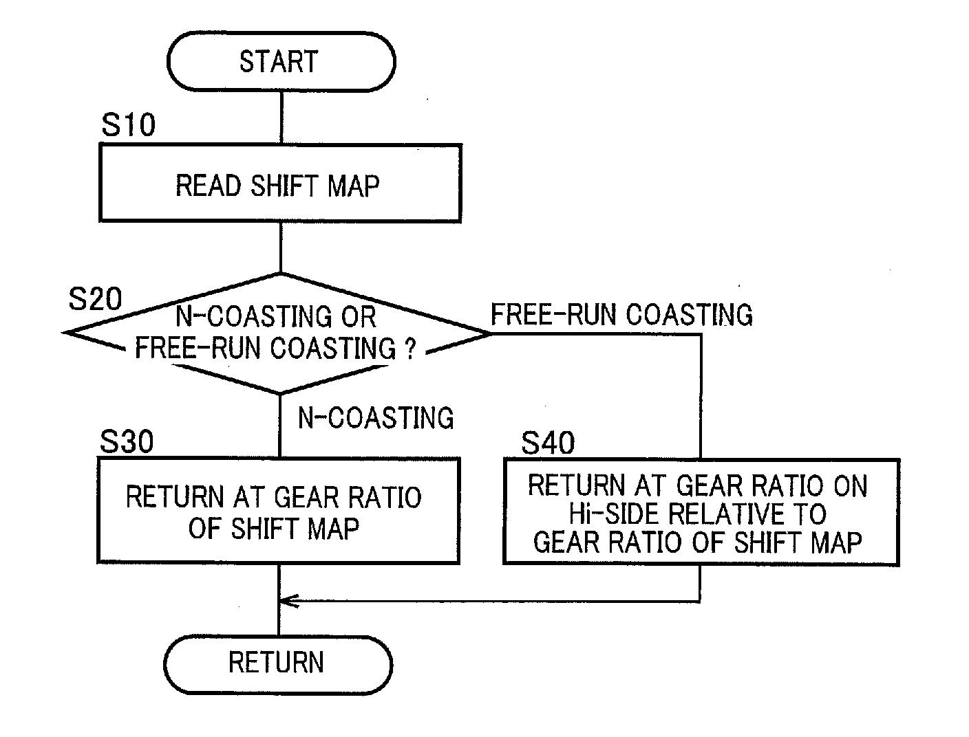
[0058]Although the gear ratio at the time of return is preliminarily established in the automatic transmission 16 except the engagement of the clutch C1 during the inertia running mode before returning to the normal running mode in the first example, alternatively, the gear ratio at the time of return is established in the automatic transmission 16 immediately before returning to the normal running mode (preferably, when a return to the normal running mode is determined) in this example.

[0059]FIG. 9 is a flowchart for explaining a main portion of the control operation of the electronic control device 70, i.e., the control operation for preventing a user from having a feeling of strangeness at the time of return from the inertia running mode to the normal running mode in terms of the responsiveness and the acceleration performance, and is repeatedly executed with an extremely short cycle time, for example, on the order of a few msec to a few tens of msec. FIG. 9 depicts another examp...


PUM


Abstract

A running control device of a vehicle including an engine, a connecting / disconnecting device separating the engine and wheels, and a transmission transmitting power of the engine toward the wheels, the running control device of a vehicle being configured to execute a normal running mode performed by using the power of the engine with the engine and the wheels coupled, a free-run inertia running mode that is an inertia running mode performed by separating the engine and the wheels and stopping the engine during running, and a neutral inertia running mode that is an inertia running mode performed by separating the engine and the wheels and operating the engine in a self-sustaining manner during running, the running control device of a vehicle setting a gear ratio of the transmission on a high vehicle speed side in the case of return from the free-run inertia running mode to the normal running mode.

Description

TECHNICAL FIELD[0001]The present invention relates to a running control device of a vehicle capable of executing an inertia running mode with an engine and wheels separated and particularly to a technique at the time of return from the inertia running mode to a normal running mode with the engine and the wheels coupled.BACKGROUND ART [0002]To extend a running distance and improve fuel consumption in a vehicle including a connecting / disconnecting device (e.g., a clutch) separating an engine and wheels and a transmission transmitting the power of the engine toward the wheels, it is conceivable that the vehicle is allowed to perform an inertia running mode when a predetermined condition is satisfied during a normal running mode performed by the power of the engine while the engine and the wheels are coupled. For example, in Patent Document 1, a control device of a vehicle is proposed that releases a clutch during running of the vehicle to separate an engine and wheels for allowing the ...

Claims


Application Information

Patent Timeline
IPC IPC(8): B60W30/182B60W10/06B60W10/10
CPCB60W30/182B60W10/10B60W2710/06B60W2710/021B60W2710/10B60W10/06B60W30/18172F16H61/0213B60W2030/1809B60W2030/18081B60W2710/105F16H2061/0234F16H2059/186F16H63/50Y02T10/60
Inventor MITSUYASU, MASAKIKIM, JONGGAPKUROKI, RENTAROHIRAI, TAKUYAMATSUNAGA, MASAKIKIDO, YASUNARISUZUKI, TAKEAKIKOGURE, TAKAYUKIOKAMURA, YUKARISATO, AKIHIROKINOSHITA, YUSUKE
Owner TOYOTA JIDOSHA KK
Features
  • Generate Ideas
  • Intellectual Property
  • Life Sciences
  • Materials
  • Tech Scout
  • Unparalleled Data Quality
  • Higher Quality Content
  • 60% Fewer Hallucinations
Learn More