Aircraft electric braking system

a technology of electric braking and aircraft, which is applied in the direction of braking systems, aircraft braking arrangements, braking components, etc., can solve problems such as partial or full loss of braking control

Active Publication Date: 2015-10-15
CRANE AEROSPACE INC +1
View PDF13 Cites 19 Cited by
  • Summary
  • Abstract
  • Description
  • Claims
  • Application Information

AI Technical Summary

Benefits of technology

[0007]The invention provides an electrically actuated braking system for an aircraft, comprising: an electro-mechanical brake actuator (EMAbrake) proximate a wheel of the aircraft, the EMAbrake including a motor; an electro-mechanical actuator controller (EMAC) including a first motor controller for generating a first drive signal for the EMAbrake, and a second motor controller for generating a second drive signal for the EMAbrake, wherein the first motor controller and the second motor controller are dissimilar so as to provide protection against common mode failure of the first and second motor controllers.

Problems solved by technology

There is a therefore a potential for simultaneous failure of several EMACs leading to partial or full loss of braking control, which is undesirable.

Method used


Image

  • Aircraft electric braking system
  • Aircraft electric braking system
  • Aircraft electric braking system

Examples


first embodiment

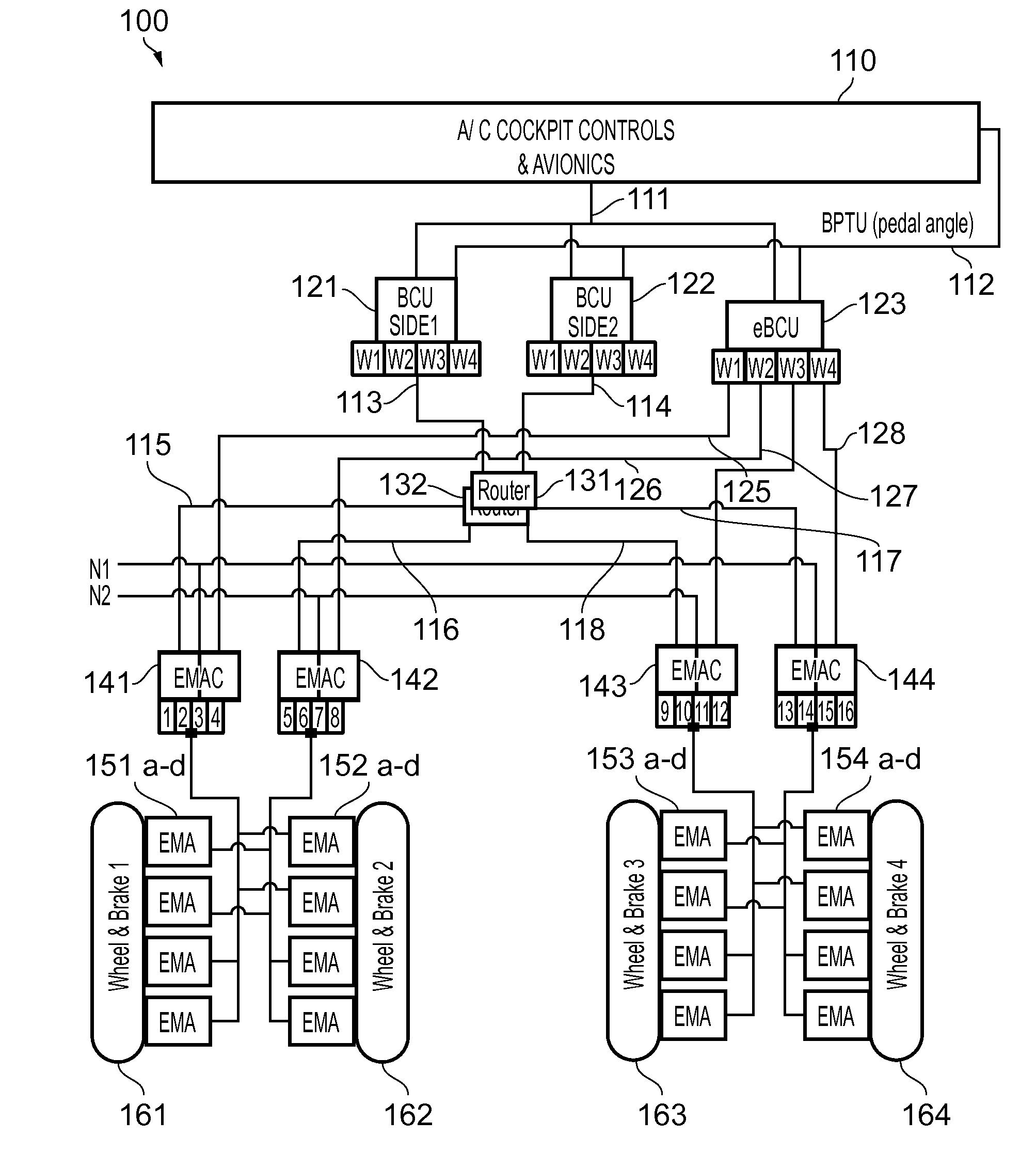
[0059]The electrically actuated aircraft braking system 100 of the first embodiment shown in FIG. 1 is configured for an aircraft having two braked main landing gears, one on either side of the aircraft centre line. However, it will be appreciated that the invention described herein relates to any aircraft configuration having braking wheels, including aircraft with more than two main landing gears and / or braked nose landing gear.

[0060]The braking system 100 features centralised avionics. The braking system includes dual redundant brake control units (BCUs) 121, 122 assigned to particular sides, e.g. aircraft avionics network or electrical power network sides (side1, side2, etc.). The BCUs 121, 122 receive input from aircraft cockpit controls and avionics 110 via one or more databuses 111 and analogue and / or discrete signals 112, e.g. from a brake pedal transmitter unit (BPTU) indicating a brake pedal angle. Note that not all signal routes are shown in the figures so as not to obscu...

second embodiment

[0084]FIG. 8 illustrates an electrically actuated aircraft braking system 200 featuring centralised avionics, and “smart” EMAs. The braking system 200 shares many similarities with the system 100 of FIGS. 1-7 and includes the following key differences. In place of the EMAs and remote EMACs of the system 100, the system 200 includes “smart” EMAs in which the normal and emergency EMAC functionality is packaged within the EMA in a single line replaceable unit (LRU). EBPSU functionality is not distributed into the EMACs, instead separate LRU EBPSUs are provided—as EBPSU functionality would need to be duplicated 16 times one for each smart EMA LRU otherwise, although this may of course be used.

[0085]The braking system 200 includes side1 and side2 BCUs 221, 222, which receive input from aircraft cockpit controls and avionics 210 via databus 211. The BCUs 221, 222 interpret signals from the aircraft cockpit controls and avionics 210 and issue braking force commands on a per wheel basis to ...

third embodiment

[0095]FIG. 11 illustrates an electrically actuated aircraft braking system 300 featuring distributed avionics, with “smart” EMACs. The braking system 300 shares many similarities with the system 100 of FIG. 1 and includes the following key differences. In place of the BCUs / eBCU and remote EMACs of the system 100, the system 300 includes “smart” EMACs in which the side1 BCU, side2 BCU and eBCU functionality is packaged within the EMAC in a single line replaceable unit (LRU). The avionics are therefore no longer centralised, but (partially) distributed.

[0096]The braking system 300 includes four smart EMACs 341-344. The smart EMACs 341-344 receive input from aircraft cockpit controls and avionics 310 via databus 311 and analogue / discrete signals 312, e.g. from a brake pedal transmitter unit (BPTU) indicating a brake pedal angle. Routers 331, 332 route digital databus signals from the aircraft cockpit controls and avionics 310 to the smart EMACs via local databuses 315-318. The smart EM...


PUM


Abstract

An electrically actuated braking system for an aircraft, comprising: an electro-mechanical brake actuator (EMAbrake) proximate a wheel of the aircraft, the EMAbrake including a motor; an electro-mechanical actuator controller (EMAC) including a first motor controller for generating a first drive signal for the EMAbrake, and a second motor controller for generating a second drive signal for the EMAbrake, wherein the first motor controller and the second motor controller are dissimilar so as to provide protection against common mode failure of the first and second motor controllers.

Description

CROSS-REFERENCE TO RELATED APPLICATION[0001]This application claims priority to GB Application No. 1320938.2, filed 27 Nov. 2013, the entire content of which is hereby incorporated by reference.FIELD OF THE INVENTION[0002]The present invention relates to an electrically actuated braking system for an aircraft.BACKGROUND OF THE INVENTION[0003]Electric systems are gradually replacing hydraulic systems on many commercial, and military, aircraft. Current “brake by wire” aircraft systems may have a generally centralised architecture in which pilot inputs are interpreted and command and monitoring signals are communicated via a databus and as analogue / discrete signals to a brake control unit (BCU). An exemplary centralised architecture is described in US 2008 / 0030069 A1.[0004]The BCU interprets the commands from the aircraft cockpit controls and avionics and calculates braking force commands for each actuated landing gear wheel of the aircraft. This may include fast loop anti-skid control...

Claims


Application Information

Patent Timeline
Patent Type & Authority Applications(United States)
IPC IPC(8): B64C25/44F16D65/14
CPCB64C25/44F16D2121/24F16D65/14B60T8/1703B60T8/885B60T2270/402B60T13/741B64C25/46B60T8/325B60T2270/404
Inventor IORDANIDIS, GEORGEREES, JOHN
Owner CRANE AEROSPACE INC
Why Eureka
Try Eureka