Separator, battery, battery pack, electronic device, electric vehicle, power storage device, and power system
a technology of separation device and battery pack, which is applied in the direction of secondary cell details, battery, electrical devices, etc., can solve the problems of air hole clogging and contraction, various problems, etc., and achieve the effect of large pore size and high porosity
Active Publication Date: 2015-10-15
MURATA MFG CO LTD
View PDF4 Cites 21 Cited by
- Summary
- Abstract
- Description
- Claims
- Application Information
AI Technical Summary
Benefits of technology
The invention provides a separator with large pores and high porosity that can absorb electrode expansion.
Problems solved by technology
However, these separators suffer from a problem in that air hole clogging and contraction occur due to the heat generated by internal short circuits or overcharging of the battery.
When the separator contracts due to the internal heat of the battery, the positive electrode and the negative electrode come into direct contact at the contracted portion, and this contact causes various problems to occur.
Method used
View moreImage
Smart ImageViewing Examples
Examples
first embodiment (
1. First embodiment (separator example)
2. Second embodiment (cylindrical battery example)
third embodiment (
3. Third embodiment (flat battery example)
4. Fourth embodiment (battery pack example)
fifth embodiment (
5. Fifth embodiment (power storage system example)
Login to View More PUM
| Property | Measurement | Unit |
|---|---|---|
| pore size | aaaaa | aaaaa |
| porosity | aaaaa | aaaaa |
| temperature | aaaaa | aaaaa |
Abstract
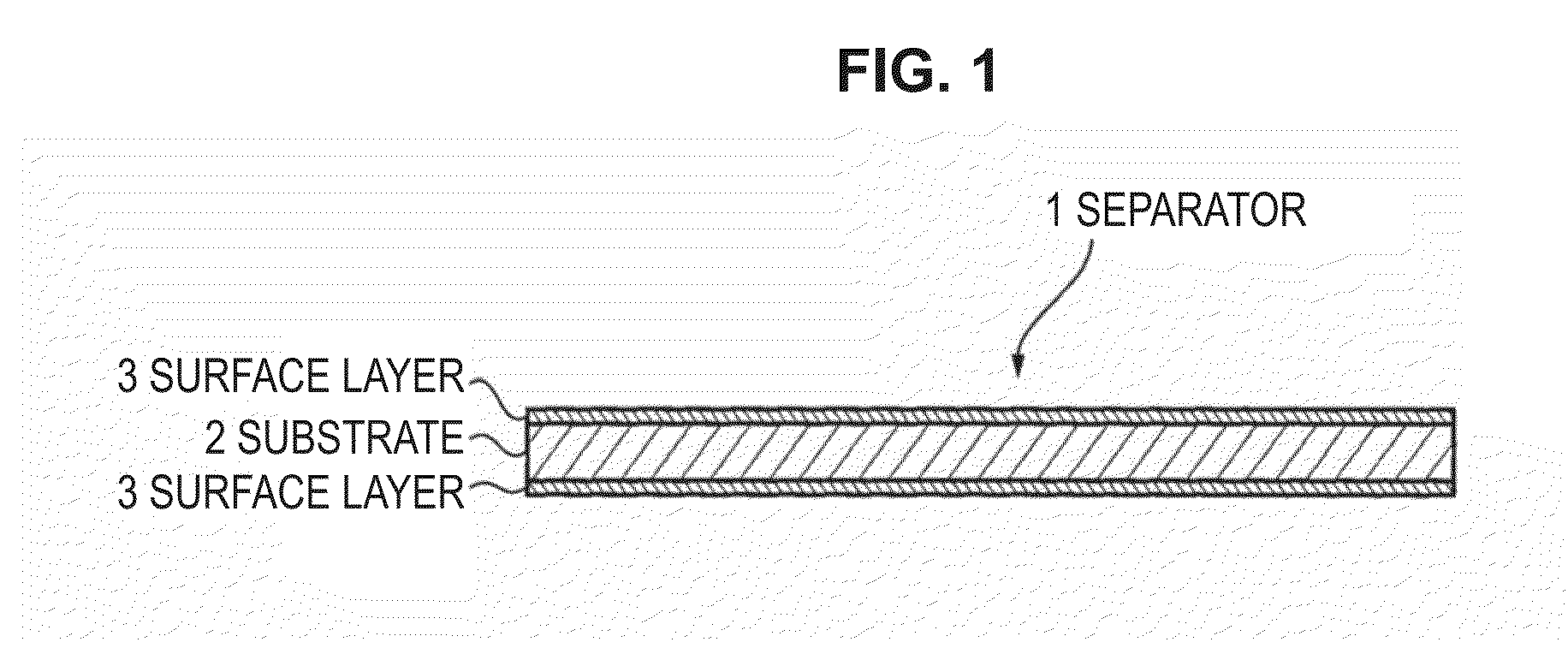
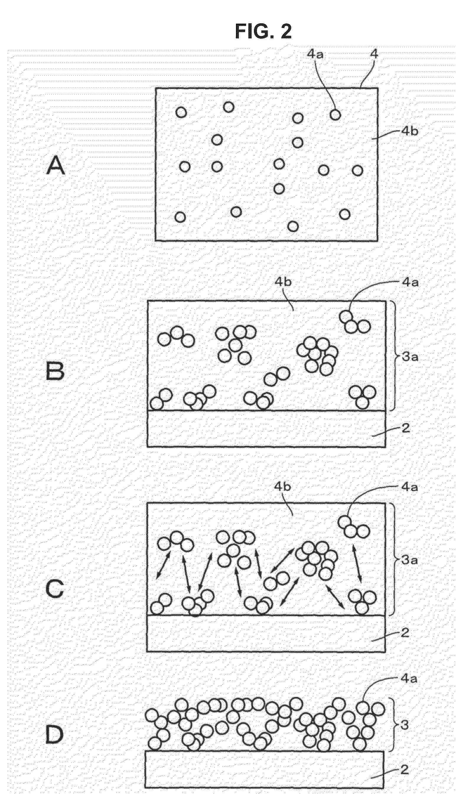
Provided is a separator including a first layer of a porous substance and a second layer that is provided on at least one face of the first layer and that includes a resin material and particles. The second layer has an agglomeration network structure of the particles.
Description
TECHNICAL FIELD[0001]The present technology relates to a separator, a battery, a battery pack, an electronic device, an electric vehicle, a power storage device, and a power system. More specifically, the present technology relates to a separator in which a second layer is provided on at least one face of a first layer.BACKGROUND ART[0002]In the past, polyolefin microporous polymer films, such as polypropylene and polyethylene, or multilayer films thereof, have been widely used as a separator. However, these separators suffer from a problem in that air hole clogging and contraction occur due to the heat generated by internal short circuits or overcharging of the battery. When the separator contracts due to the internal heat of the battery, the positive electrode and the negative electrode come into direct contact at the contracted portion, and this contact causes various problems to occur.[0003]Accordingly, recently, to solve these problems with the separator, research has been carr...
Claims
Login to View More Application Information
Patent Timeline
 Patent Type & Authority Applications(United States)
IPC IPC(8): H01M2/16H02J7/00H01M10/0525H01M50/417H01M50/426H01M50/434H01M50/449
CPCH01M2/1686H01M10/0525H02J2007/0096H01M2220/20H02J7/0068H01M10/052H01M50/449H02J7/0047H02J7/0048H02J7/0013H01M50/426H01M50/434H01M50/417H02J7/00034Y02E60/10Y02T10/70H01M50/446H01M50/491H01M50/414H01M50/443H01M50/431H01M4/38H01M10/02H01M50/20H01M10/425H01M2010/4278Y02P70/50
Inventor OKUNO, MORIAKI
Owner MURATA MFG CO LTD
Features
- R&D
- Intellectual Property
- Life Sciences
- Materials
- Tech Scout
- Unparalleled Data Quality
- Higher Quality Content
- 60% Fewer Hallucinations
Learn More Browse by: Latest US Patents, China's latest patents, Technical Efficacy Thesaurus, Application Domain, Technology Topic, Popular Technical Reports.
© 2025 PatSnap. All rights reserved.Legal|Privacy policy|Modern Slavery Act Transparency Statement|Sitemap|About US| Contact US: help@patsnap.com


