Using demand side resources to provide frequency regulation

a demand side resource and frequency regulation technology, applied in the field of electric power grid arts and electrical power grid frequency control arts, can solve the problems of reducing electrical frequency, slowing mechanical rotation and consequently lowering electrical frequency, and a direct cost to the utility or other grid operator, and reducing the cost of construction and maintenance of frequency control devices. , the effect of reducing the overhead cost and energy waste of the power grid

Active Publication Date: 2015-10-15
BATTELLE MEMORIAL INST
View PDF8 Cites 11 Cited by
  • Summary
  • Abstract
  • Description
  • Claims
  • Application Information

AI Technical Summary

Problems solved by technology

If the load increases, this creates counter-torque on the generators which slows the mechanical rotation and consequently lowers the electrical frequency.
In the former case, construction and maintenance of these frequency control devices is a direct cost to the utility company or other grid operator.
The requirement to maintain sufficient ancillary generator capacity available for frequency control introduces substantial overhead cost and energy waste to the power grid.
Overhead cost arises due to the need to construct and maintain the ancillary generators, and / or the cost of contracting with CSPs for access to these devices.
Energy waste arises due to operational inefficiencies of the ancillary generators (or batteries, flywheels, et cetera).
Frequency response loads can in principle improve frequency regulation, but the decentralized nature of this approach limits its usefulness.
The grid operator does not control the frequency response loads, and so cannot rely upon these loads to maintain the target frequency.
(Indeed, it is possible that a high density of frequency response loads may actually be detrimental, if the load modeling employed by the grid operator does not take these loads into account).

Method used


Image

  • Using demand side resources to provide frequency regulation
  • Using demand side resources to provide frequency regulation
  • Using demand side resources to provide frequency regulation

Examples


Embodiment Construction

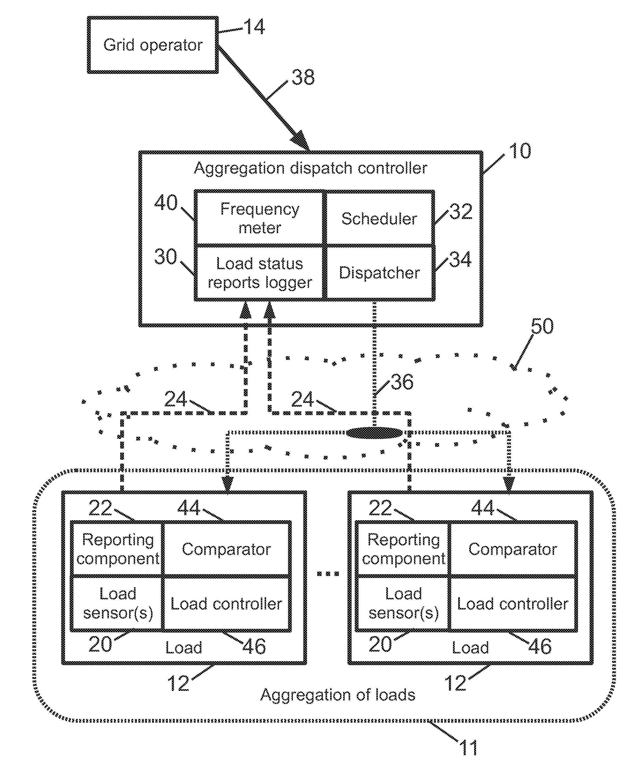
[0014]Disclosed herein are approaches for control of loads that balances the objectives of providing power grid frequency control, on the one hand, and efficiently operating the individual loads, on the other hand. These objectives are not necessarily in concert. For example, when the grid is in an under-frequency condition the grid operator may wish to reduce the power draw of the loads; however, if the stored water temperature in a hot water tank is approaching its low temperature threshold then power must be drawn immediately to maintain water temperature. Conversely, if the grid is in an over-frequency condition and needs additional load, but the stored water temperature in a hot water tank is approaching its high temperature threshold, then power that hot water tank may not draw any heating power at that time.

[0015]In the case of large industrial loads under DLC, it may be feasible to provide individualized DLC control for each load that balances the potentially contradictory o...


PUM


Abstract

In a direct load control system supporting frequency control of an electrical grid, at each electrical load of an aggregation of loads, a load status report is generated comprising an urgency value and a power level. At an aggregation dispatch controller, a dispatch signal is generated based on the generated load status reports and information indicative of electrical frequency. At each electrical load of the aggregation, the load is operated at the reported power level if the reported urgency value satisfies the dispatch signal and is not operated at the reported power level if the reported urgency value does not satisfy the dispatch signal.

Description

[0001]This application claims the benefit of U.S. Provisional Application No. 61 / 734,537 filed Dec. 7, 2012 titled “Method and System for Using Demand Side Resources to Provide Frequency Regulation Using a Dynamic Allocation of Energy Resources”. This application also claims the benefit of U.S. Provisional Application No. 61 / 789,169 filed Mar. 15, 2013 titled “Method and System for Using Demand Side Resources to Provide Frequency Regulation Using a Dynamic Allocation of Energy Resources”.[0002]U.S. Provisional Application No. 61 / 734,537 filed Dec. 7, 2012 titled “Method and System for Using Demand Side Resources to Provide Frequency Regulation Using a Dynamic Allocation of Energy Resources” is incorporated herein by reference in its entirety. U.S. Provisional Application No. 61 / 789,169 filed Mar. 15, 2013 titled “Method and System for Using Demand Side Resources to Provide Frequency Regulation Using a Dynamic Allocation of Energy Resources” is incorporated herein by reference in its...

Claims


Application Information

Patent Timeline
Patent Type & Authority Applications(United States)
IPC IPC(8): H02J3/00G05B15/02
CPCG05B15/02H02J3/00Y04S40/121Y04S40/124Y04S40/126H02J13/00007H02J2310/12H02J13/00016H02J13/00024H02J13/00026H02J13/00004H02J3/14Y02B90/20Y04S20/12H02J2310/58Y02B70/3225Y04S20/222H02J7/00036H02J7/02H02J9/062H02J4/00
Inventor BLACK, JASON W.MCCULLOUGH, JASON J.REHBERG, ERICDVORSKY, JAMES E.MANSOURI, SEYED A.
Owner BATTELLE MEMORIAL INST
Why Eureka
Try Eureka