Light emitting diode driving apparatus with variable output current and method for the same

a technology of light emitting diodes and driving apparatuses, which is applied in the direction of electric variable regulation, process and machine control, instruments, etc., can solve the problem of not and achieve the effect of easily changing the output current of the light emitting diodes driving apparatus

Active Publication Date: 2015-10-15
CHICONY POWER TECH CO LTD
View PDF1 Cites 3 Cited by
  • Summary
  • Abstract
  • Description
  • Claims
  • Application Information

AI Technical Summary

Benefits of technology

[0012]The efficiency of the present invention is to change the output current of the light emitting diode driving apparatus easily.

Problems solved by technology

However, the disadvantage of the light emitting diode driving apparatus is that the output current of the light emitting diode driving apparatus is not changed easily.

Method used


Image

  • Light emitting diode driving apparatus with variable output current and method for the same
  • Light emitting diode driving apparatus with variable output current and method for the same
  • Light emitting diode driving apparatus with variable output current and method for the same

Examples


first embodiment

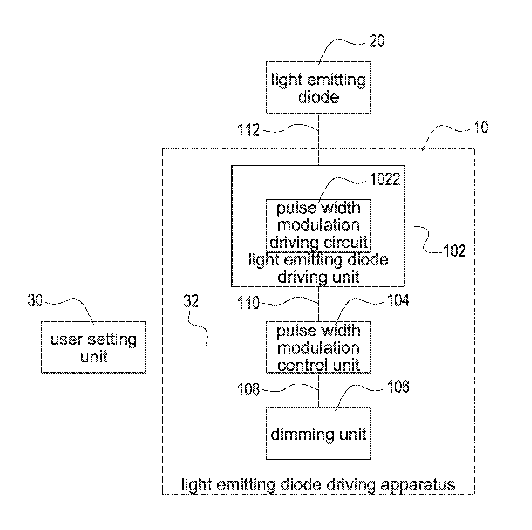
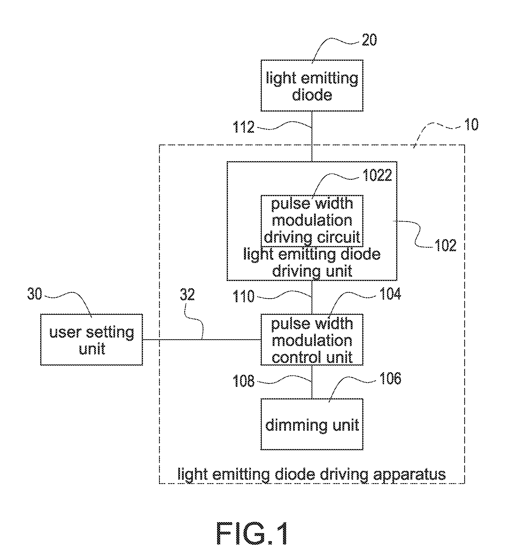
[0016]FIG. 1 shows a block diagram of the light emitting diode driving apparatus of the present invention. A light emitting diode driving apparatus 10 with variable output currents is applied to at least a light emitting diode 20 and a user setting unit 30. The light emitting diode driving apparatus 10 includes a light emitting diode driving unit 102, a pulse width modulation control unit 104 and a dimming unit 106.

[0017]The light emitting diode driving unit 102 is electrically connected to the light emitting diode 20. The pulse width modulation control unit 104 is electrically connected to the light emitting diode driving unit 102 and the user setting unit 30. The dimming unit 106 is electrically connected to the pulse width modulation control unit 104.

[0018]The user setting unit 30 sends a user side setting signal 32 to the pulse width modulation control unit 104. The dimming unit 106 sends a dimming signal 108 to the pulse width modulation control unit 104. The pulse width modula...

second embodiment

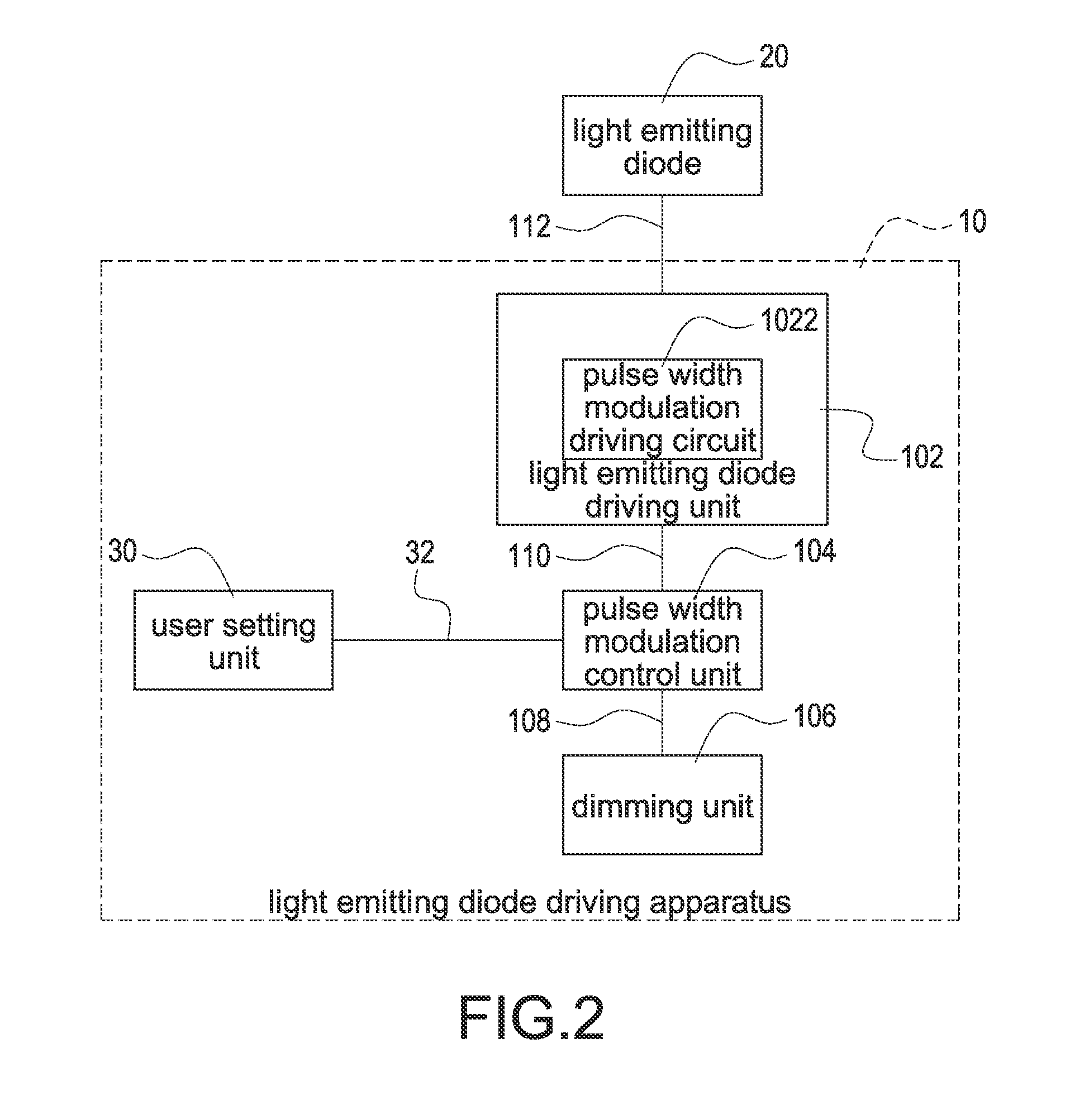
[0024]FIG. 2 shows a block diagram of the light emitting diode driving apparatus of the present invention. A light emitting diode driving apparatus 10 with variable output current is applied to at least a light emitting diode 20. The light emitting diode driving apparatus 10 includes a user setting g unit 30, a light emitting diode driving unit 102, a pulse width modulation control unit 104 and a dimming unit 106.

[0025]The light emitting diode driving unit 102 is electrically connected to the light emitting diode 20. The pulse width modulation control unit 104 is electrically connected to the light emitting diode driving unit 102 and the user setting unit 30. The dimming unit 106 is electrically connected to the pulse width modulation control unit 104.

[0026]The user setting unit 30 sends a user side setting signal 32 to the pulse width modulation control unit 104. The dimming unit 106 sends a dimming signal 108 to the pulse width modulation control unit 104. The pulse width modulati...


PUM


Abstract

A pulse width modulation control unit multiplies a value of a user side setting signal by a value of a dimming signal to obtain a pulse width modulation output current control signal. The pulse width modulation control unit sends the pulse width modulation output current control signal to a light emitting diode driving unit. The light emitting diode driving unit multiplies a value of the pulse width modulation output current control signal by a value of a maximum output current of the light emitting diode driving unit to obtain a light emitting diode pulse width modulation driving current. The light emitting diode driving unit drives a light emitting diode by the light emitting diode pulse width modulation driving current.

Description

BACKGROUND OF THE INVENTION[0001]1. Field of the Invention[0002]The present invention relates to a light emitting diode driving apparatus and a method for outputting current of the light emitting diode driving apparatus, and especially relates to a light emitting diode driving apparatus with variable output current and method for the same.[0003]2. Description of the Related Art[0004]Comparing to incandescent light sources, light emitting diodes have a lot of advantages, including lower energy consumption, longer life, improved physical endurance, smaller size and faster switching speed. Therefore, light emitting diodes are used widely to replace fluorescent lamps or tungsten lamps.[0005]A light emitting diode driving apparatus is used to drive light emitting diodes. However, the disadvantage of the light emitting diode driving apparatus is that the output current of the light emitting diode driving apparatus is not changed easily. Generally speaking, the hardware of the light emitti...

Claims


Application Information

Patent Timeline
Patent Type & Authority Applications(United States)
IPC IPC(8): H05B33/08H05B44/00
CPCH05B33/0845H05B45/10
Inventor TSAI, CHAO-WEIWANG, JYUN-PINGSHIH, HUNG-TA
Owner CHICONY POWER TECH CO LTD
Why Eureka
Try Eureka