Garment hanger

a technology for hanging racks and garments, applied in garments, garments, applications, etc., can solve the problems of shortening the strength of unable to design the hooks to have a sufficiently large diameter, and excessive load on the hooks of the hangers, so as to ensure the effect of attaching the hooks to the hangers

Inactive Publication Date: 2015-10-22
MARUSO IND
View PDF0 Cites 10 Cited by
  • Summary
  • Abstract
  • Description
  • Claims
  • Application Information

AI Technical Summary

Benefits of technology

[0019]In view of the above-mentioned problems in the conventional garment hangers, it is an object of the present invention to provide a garment hanger making it possible to readily attach a hook to a hanger body, and further, not allowing a hook to be released out of a hanger body, if a force acts on the hook.

Problems solved by technology

Accordingly, since clothes hung from a hanger are caused to swing while being carried, resulting in that an excessive load acts on a hook of the hanger.
Since a diameter of the hook of the hanger carried along a rail is limited to a specific range of a diameter, it is not allowed to design the hook to have a sufficiently great diameter for the purpose of providing sufficient strength to the hook.
Consequently, a hanger composed of a resin would be short of strength of a hook.

Method used


Image

  • Garment hanger
  • Garment hanger
  • Garment hanger

Examples


first embodiment

[0065]First, elements of a shirt to be hung by a garment hanger (hereinafter often referred to simply as a “hanger”) are explained with reference to FIG. 7.

[0066]As illustrated in FIG. 7, a dress shirt includes a collar 81 comprising a rear collar portion 82, a front collar portion 84, and a pair of side collar portions 83 connecting the front collar portion 84 and the rear collar portion 82 to each other. As mentioned below, the dress shirt is hung by the hanger in accordance with the preferred embodiments of the present invention.

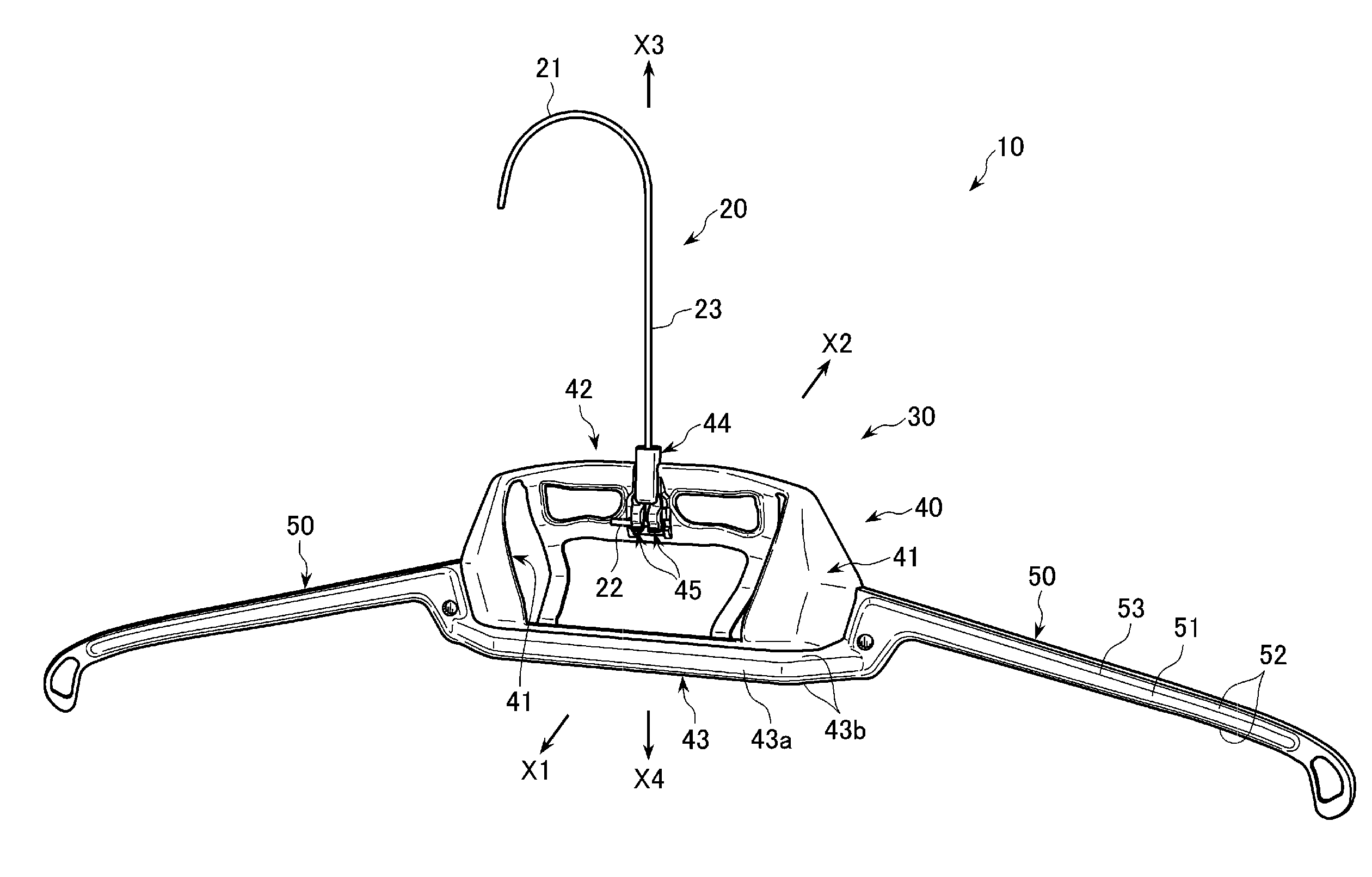
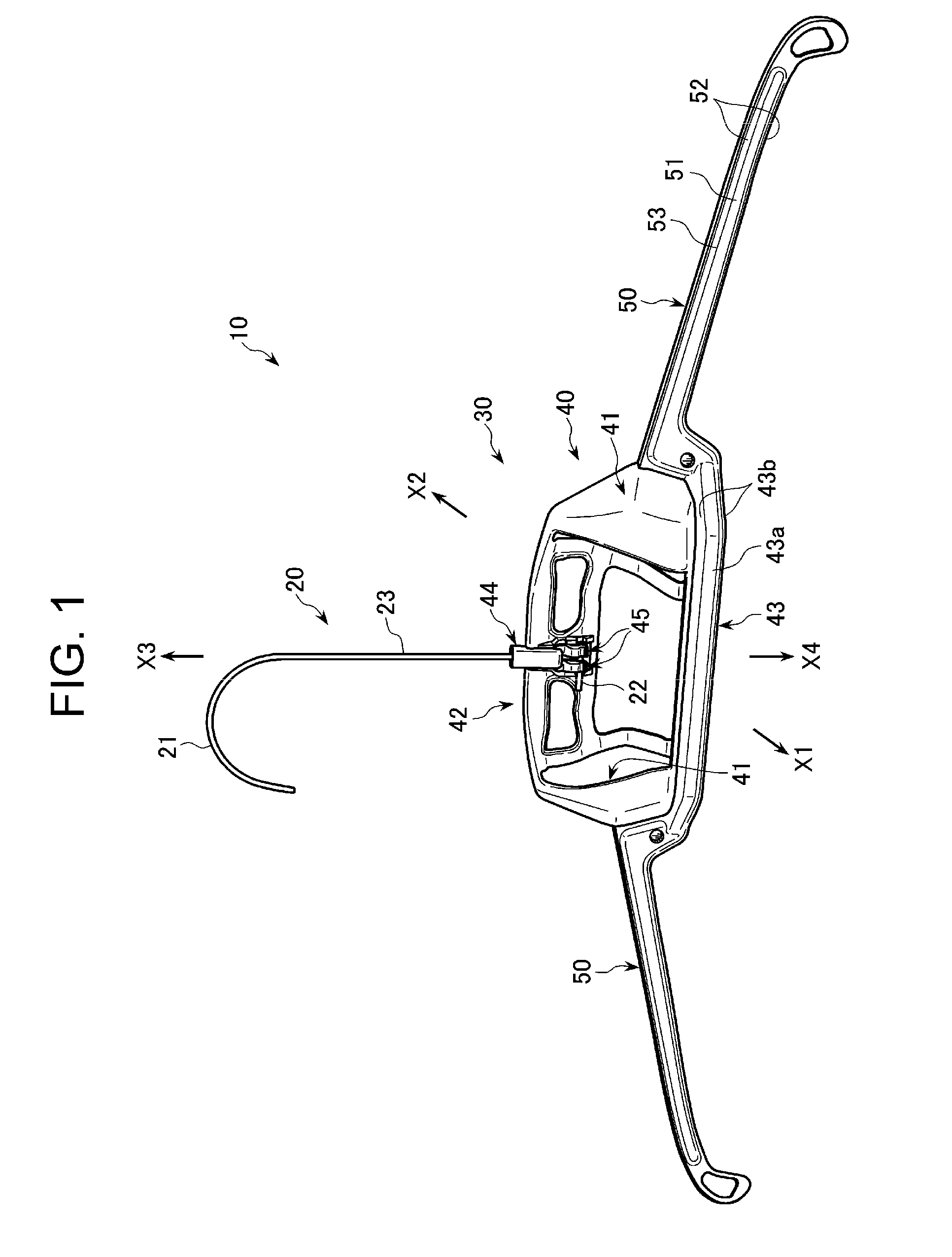
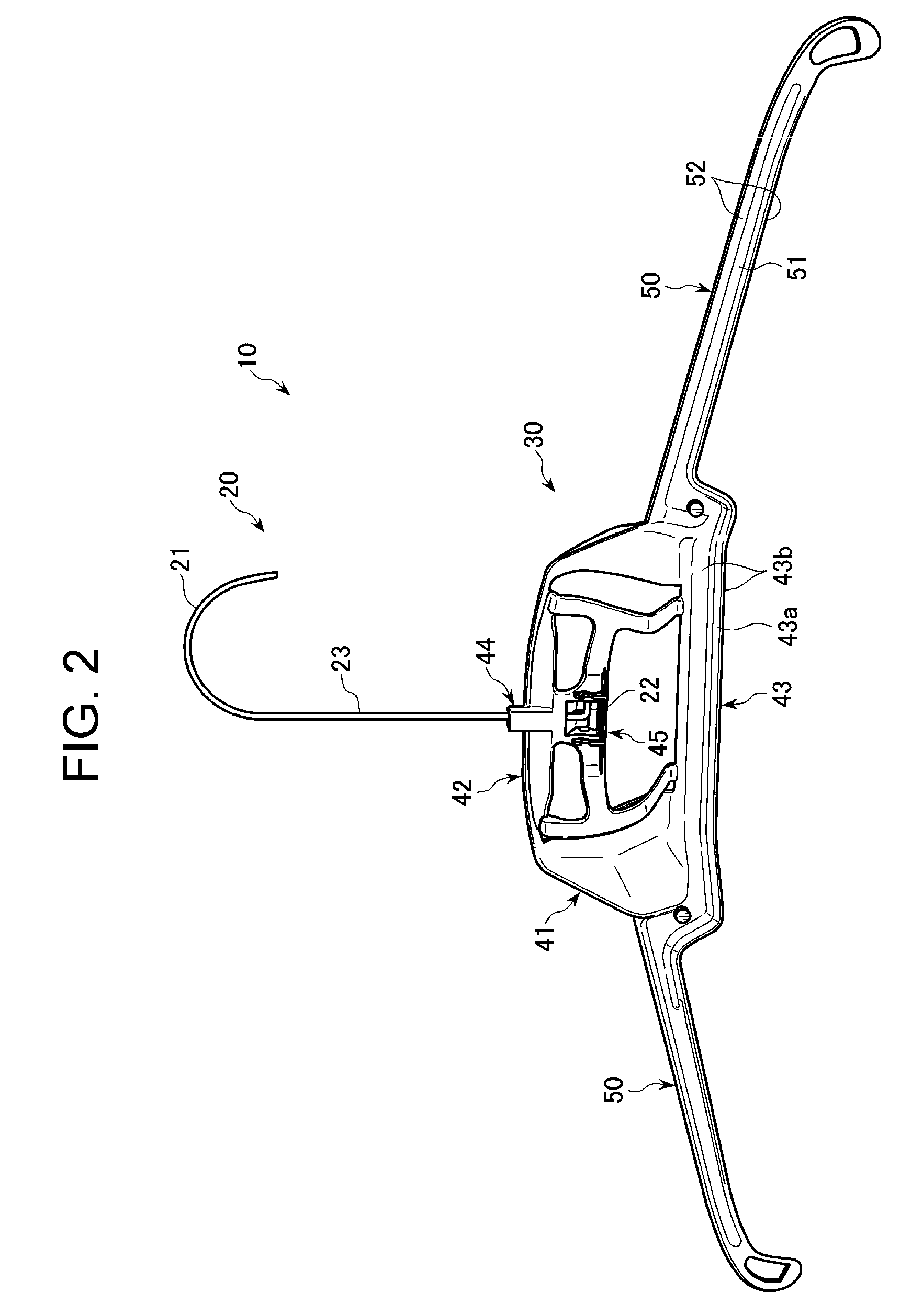
[0067]A hanger 10 in accordance with the first embodiment is explained hereinbelow with reference to the drawings.

[0068]The hanger 10 holds the collar 81 and shoulders of a jacket, a shirt and so on.

[0069]As illustrated in FIGS. 1 to 4, the hanger 10 includes a hook 20, and a hanger body 30 by which a dress shirt is held.

[0070]In the specification, a front or a forward relative to the hanger 10 indicates a direction X1, a rear or a back relative to the ha...

second embodiment

[0104]A hanger 10x in accordance with the second embodiment of the present invention is explained hereinbelow with reference to FIGS. 8 to 14. Parts or elements of the hanger 10x that correspond to those of the hanger 10 illustrated in FIGS. 1 to 4 have been provided with the same reference numerals, and operate in the same manner as corresponding parts or elements in the first embodiment, unless explicitly explained hereinbelow.

[0105]As illustrated in FIGS. 8 to 13, the shaft guide 44 in the hanger 10x in accordance with the second embodiment is designed to include a first shaft receiver 44a, a second shaft receiver 44b and a third shaft receiver 44c each of which receives the shaft portion 23 of the hook 20 along an axis of the shaft portion 23. The first shaft receiver 44a is located uppermost among the first to third shaft receivers, and the third shaft receiver 44c is located lowermost among the first to third shaft receivers.

[0106]The first shaft receiver 44a includes a groove...

third embodiment

[0143]A hanger 10y in accordance with the third embodiment of the present invention is explained hereinbelow with reference to FIGS. 18 and 19. Parts or elements of the hanger 10y that correspond to those of the hanger 10x illustrated in FIGS. 18 to 11 have been provided with the same reference numerals, and operate in the same manner as corresponding parts or elements in the second embodiment, unless explicitly explained hereinbelow.

[0144]As illustrated in FIGS. 18 and 19, the shaft guide 44y in the hanger 10y in accordance with the third embodiment is designed to include a second shaft receiver 44b and a third shaft receiver 44c each of which receives the shaft portion 23 of the hook 20 along an axis of the shaft portion 23. The second shaft receiver 44a is located above the third shaft receiver 44c. That is, the hanger 10y is designed not to include the first shaft receiver 44a relative to the shaft guide 44x of the hanger 10x in accordance with the second embodiment.

[0145]The sh...


PUM


Abstract

A garment hanger includes a hook composed of a metal wire, and a hanger body to which the hook is detachably connected for holding clothes therearound, the hanger body being integrally formed of a resin, the hook including a hook portion, a bending portion through which the hook is connected to the hanger body, and a shaft portion connecting the hook portion and the bending portion to each other, the hanger body including a shaft guide formed therethrough with a path through which the shaft portion of the hook is inserted, and a hook-receiving unit to which the bending portion is engaged and in which the bending portion is housed when the bending portion is pulled up with the shaft portion being inserted into the path of the shaft guide, to thereby connect the hook to the hanger body.

Description

BACKGROUND OF THE INVENTION[0001]1. Field of the Invention[0002]The invention relates to a garment hanger for holding clothes, including a hook composed of a metal wire, and a hanger body integrally formed of a resin, capable of preventing a jacket from losing original shape thereof at a collar and shoulders.[0003]2. Description of the Related Art[0004]Clothes such as jackets for men and jackets and one-pieces for women, having been cleaned in a laundry shop are kept hung by means of a garment hanger (hereinafter often referred to simply as a “hanger”) for preventing those clothes from being wrongly deformed to thereby lose original shape thereof, until they are handed to consumers.[0005]In a cleaning factory, clothes are held by a hanger and hung from a rail arranged in the factory. Clothes are carried in the factory together with a hanger. Accordingly, since clothes hung from a hanger are caused to swing while being carried, resulting in that an excessive load acts on a hook of th...

Claims


Application Information

Patent Timeline
Patent Type & Authority Applications(United States)
IPC IPC(8): A47G25/32A47G25/24
CPCA47G25/24A47G25/32A47G25/1442A47G25/20
Inventor YAMADA, OSAMU
Owner MARUSO IND
Why Eureka
Try Eureka