Flow system for medical lines

a flow system and medical line technology, applied in the direction of suction devices, valves, intravenous devices, etc., can solve the problems of fluid contamination and leakage, and achieve the effect of avoiding any contamination risk

Active Publication Date: 2015-10-22
IND BORLA
View PDF3 Cites 55 Cited by
  • Summary
  • Abstract
  • Description
  • Claims
  • Application Information

AI Technical Summary

Benefits of technology

[0006]The object of the present invention is to overcome the above drawback and to provide a flow system for medical lines of the type defined in the pre-characterizing part of claim 1 (and generally corresponding to what is desc

Problems solved by technology

This arrangement, in addition to being relatively complicated, may entail the risk of the valve being opened by the auxiliary slider before the male luer-c

Method used


Image

  • Flow system for medical lines
  • Flow system for medical lines
  • Flow system for medical lines

Examples


Embodiment Construction

[0018]The flow system according to the invention represented in the drawings may be applied in particular to a medical haemodialysis line.

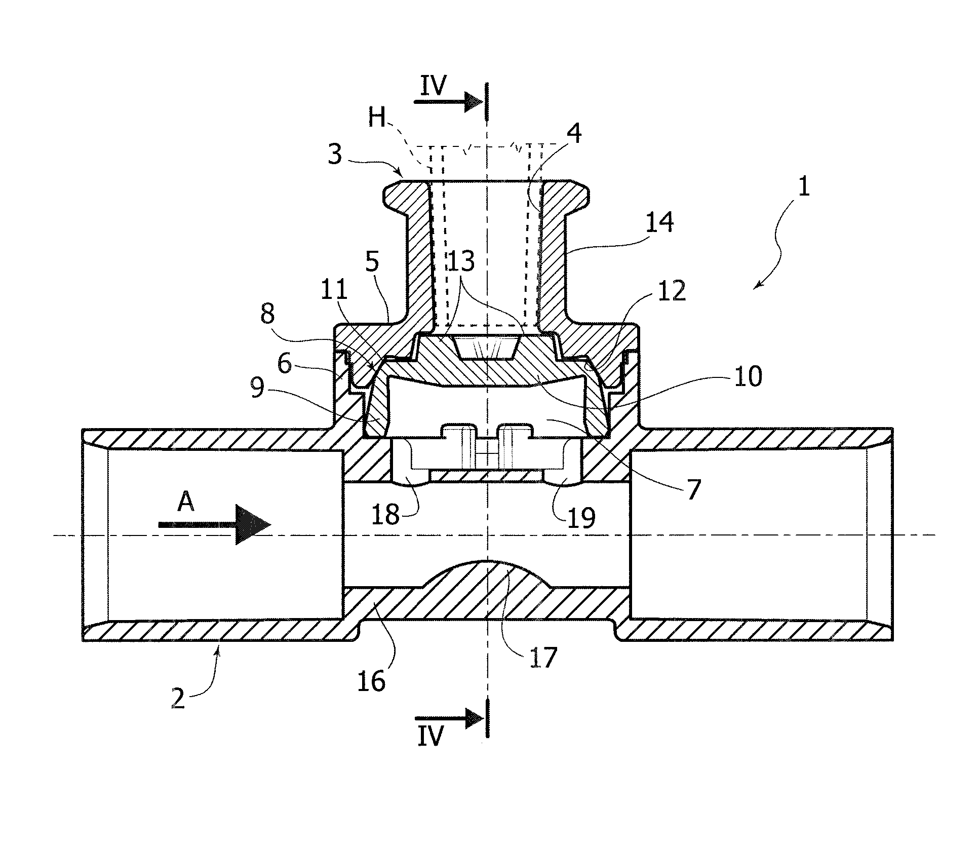
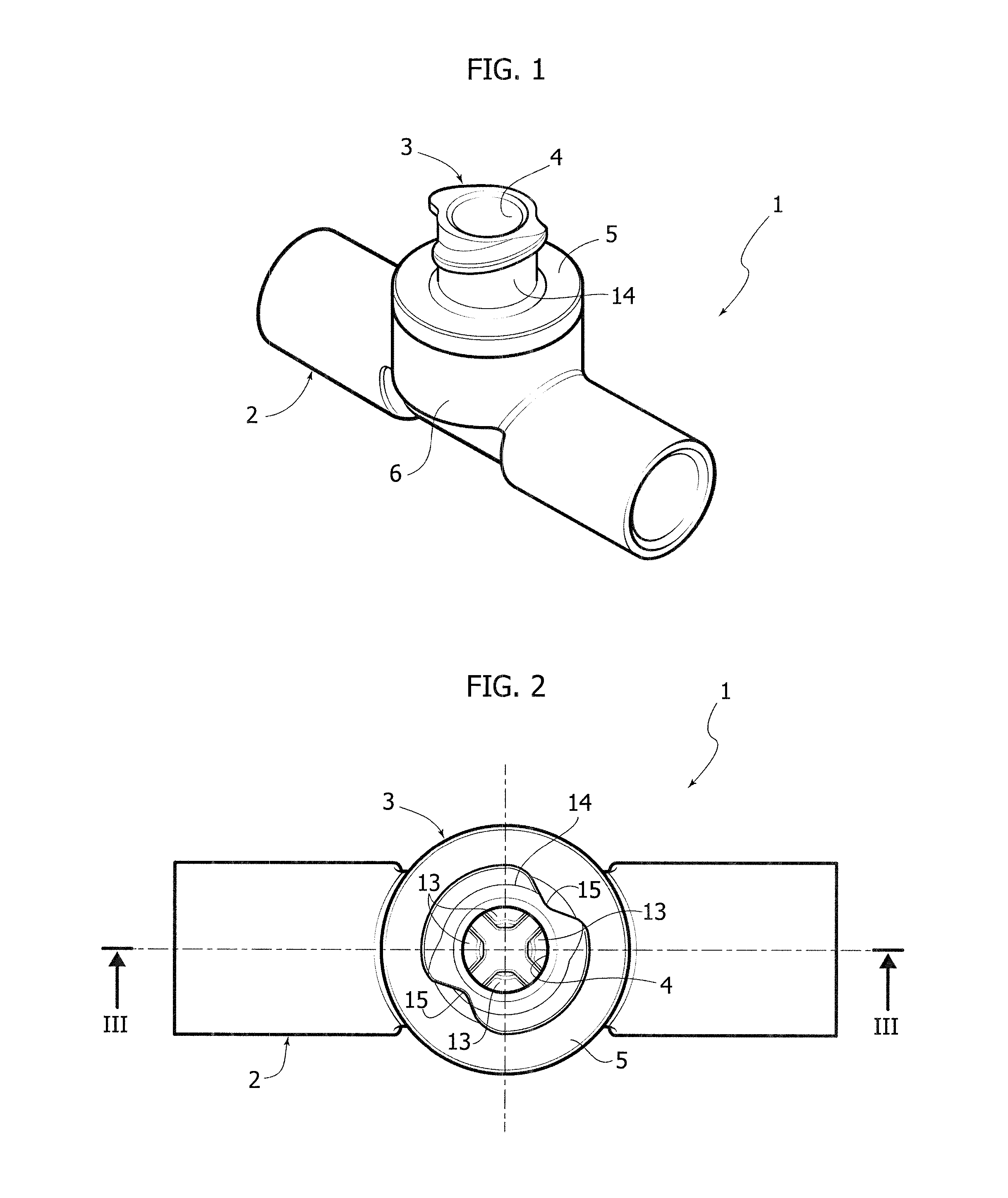
[0019]The flow system basically comprises a flow component 1 having a main duct 2 designed in use to be traversed by the flow of a primary fluid in the direction indicated by the arrow A, and a lateral tubular fitting 3 extending in a direction perpendicular to the duct 2 for introduction of a secondary fluid into the latter.

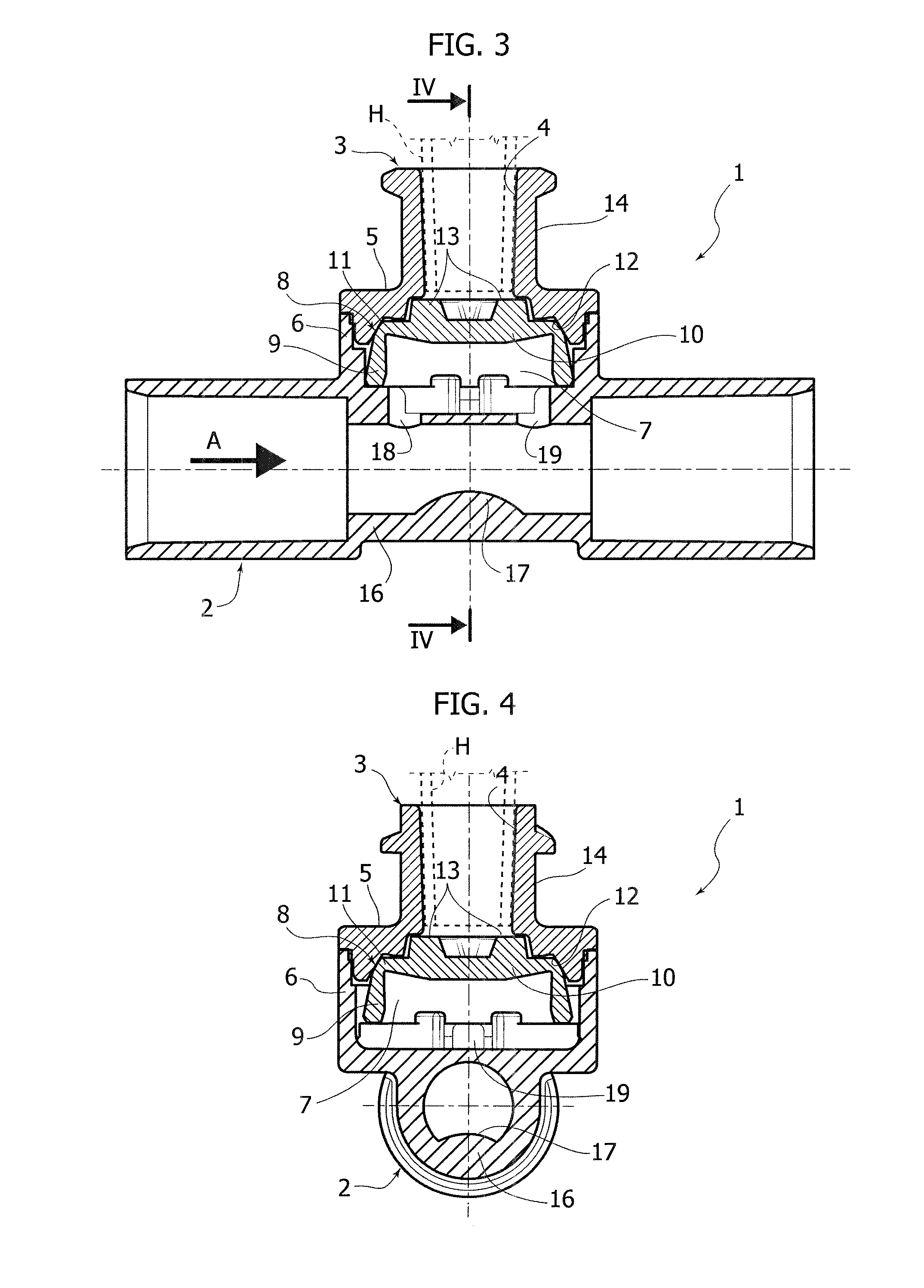
[0020]The lateral tubular fitting 3 is shaped like a female luer-lock connector, the luer-cone internal surface of which is designated by 4, and the internal end of which has an annular flange 5 fixed in a fluid-tight way at an annular collar 6 projecting laterally from the main duct 2.

[0021]Defined between the annular flange 5 and the annular collar 6 is a chamber 7 for a two-way valve, the general conformation of which is known from the already cited European patents Nos. EP-B-1093828 and EP-B-1661599. In detail, and as is m...


PUM


Abstract

A flow system for medical lines includes a flow component having a main duct and at least one lateral tubular fitting with a female luer cone communicating with the main duct) through a valve. The valve includes a transverse diaphragm normally kept in fluid-tight contact against an annular valve seat of the lateral tubular fitting, which can be moved away from this into an opening position following upon insertion of a male luer-cone introducer of fluid into the lateral tubular fitting. The diaphragm is prearranged for being pushed into the opening position directly by the introducer, and the lateral tubular fitting is configured to couple in a fluid-tight way with the introducer before the latter comes into contact of thrust with the diaphragm.

Description

FIELD OF THE INVENTION[0001]The subject of the present invention is a flow system for medical lines, in particular for haemodialysis, of the type comprising a flow component having a main duct for a primary fluid and at least one lateral tubular fitting with female luer cone communicating with the main duct through a valve.PRIOR ART[0002]A flow component of the type defined above is known from the European patent No. EP-B-1661599 filed in the name of the present applicant, in which the valve is a so-called anti-siphon valve, including a diaphragm constituted by the bottom wall of a cup-shaped element made of elastically deformable material, the outer peripheral edge of which is normally kept in fluid-tight contact against an annular valve seat of the lateral tubular fitting. As is also described in the patent No. EP-B-1093828, which is also filed in the name of the present applicant, the sealing edge of this valve can be moved away from the corresponding annular valve seat, to an op...

Claims


Application Information

Patent Timeline
IPC IPC(8): A61M1/36A61M39/10A61M39/22
CPCA61M1/367A61M39/10A61M39/22A61M39/26A61M2039/1083A61M2039/2433A61M2039/246A61M2039/261
Inventor GUALA, GIANNI
Owner IND BORLA
Why Eureka
Try Eureka