Method for manufacturing pneumatic tire

Inactive Publication Date: 2015-10-22
SUMITOMO RUBBER IND LTD
View PDF4 Cites 2 Cited by
  • Summary
  • Abstract
  • Description
  • Claims
  • Application Information

AI Technical Summary

Benefits of technology

[0013]In the present invention, a pneumatic tire is manufactured by the core method. Employed as a band cord in the pneumatic tire is a composite cord in which a first strand formed of an aramid fiber and a second strand formed of a heat-shrinkable organic fiber are twisted together.
[0014]During vulcanization shaping, the second strand in the composite cord shrinks by heat. Thus, even in the case of using the core method without vulcanization stretch, the composite cord shrinks in the tire and undergoes tension. Accordingly, it is possible to suppress looseness and snaking of the band cord and thus prevent fracture of the band cord.
[0015]The composite cord has an elongation within a range of 0.9% to 3.3% at an inflection point of its stress-elongation curve. The composite cord has a low-elastic region and a modulus in the low-elastic region within a range of 11N/% to 31N/%. If the elongation of the composite cord at the inflection point exceeds 3.3%, the binding force of the composite cord to the belt layer becomes insufficient during high-speed running at which a large centrifugal force acts on the tire, and thus improvement of high-speed durability cannot be ex

Problems solved by technology

This lifting causes delamination damage to the tire at an axially outer end of a belt layer as a starting point.
Therefore, the lifting exerts large influence on high-speed durability of the pneumatic tire.
Therefore, if a nylon cord having a small modulus is employed as a band cord of the tire, the band cord has an insufficient binding force to the belt layer and it is thus difficult to suppress lifting.
Ho

Method used


Image

  • Method for manufacturing pneumatic tire
  • Method for manufacturing pneumatic tire
  • Method for manufacturing pneumatic tire

Examples


Example

[0024]one embodiment of the present invention will be described below with reference to the drawings.

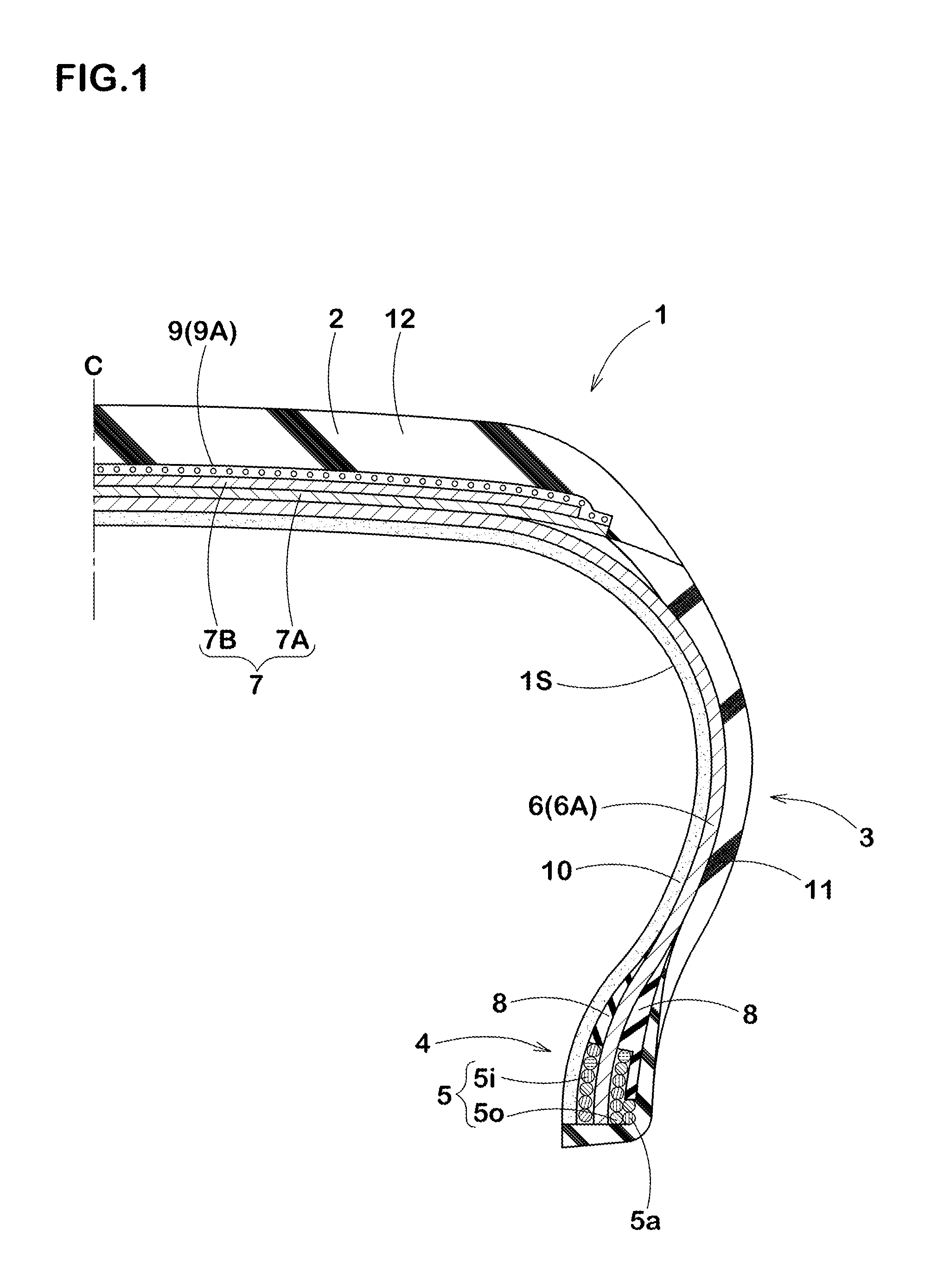
[0025]FIG. 1 is a cross-section view of one embodiment of a pneumatic tire 1 manufactured by a manufacturing method of the present invention. The pneumatic tire 1 includes a carcass 6 extending from a tread portion 2 through a side wall portion 3 to bead portions 4, a belt layer 7 disposed radially outward of the carcass 6 in the tread portion 2, and a band layer 9 disposed radially outward of the belt layer.

[0026]The carcass 6 includes at least one, in this example, one carcass ply 6A in which a carcass cord is arranged in a radial direction of the tire. The carcass ply 6A has a toroidal shape extending between a pair of bead portions 4 and 4. A bead core 5 is arranged at each of the bead portions 4. The bead core 5 comprises an axially inner core piece 5i and an axially outer core piece 5o. Both end portions of the carcass ply 6A are terminated at the position of the bead core 5 ar...


PUM

PropertyMeasurementUnit
Fractionaaaaaaaaaa
Fractionaaaaaaaaaa
Heataaaaaaaaaa

Abstract

A manufacturing method using a rigid core, wherein high-speed endurance performance is enhanced while breakage of band cords is suppressed. This method for manufacturing a pneumatic tire includes a green tire formation process for forming a green tire by affixing tire-constituting members in sequence to a rigid core. The green tire formation process includes a band ply formation step for winding a ribbon-shaped strip in which a band cord sequence is coated with a topping rubber into a helical shape. The band cord comprises a composite cord in which first strands of aramid fiber and second strands of heat-shrinkable organic fiber are twisted together. The stress-elongation curve of the composite cord has a low-elasticity region from the origin to the inflection point, and a high-elasticity region past the inflection point. The elongation of the composite cord is in the range of 0.9-3.3% at the inflection point, and the modulus of the composite cord is in the range of 11-31 N/% in the low-elasticity region.

Description

TECHNICAL FIELD[0001]The present invention relates to a method for manufacturing a pneumatic tire using a rigid core.BACKGROUND ART[0002]A pneumatic tire of a radial structure exhibits a phenomenon called lifting that a tread portion bulges radially outwardly due to centrifugal force during rotation. This lifting causes delamination damage to the tire at an axially outer end of a belt layer as a starting point. Therefore, the lifting exerts large influence on high-speed durability of the pneumatic tire. To suppress occurrence of such lifting, it has been suggested to provide a band ply on the belt layer. The band layer includes a band cord of organic fiber being wound in a spiral form. Such a band ply suppresses lifting by hoop effect.[0003]There is a conventionally known method for manufacturing a pneumatic tire including the steps of forming a green tire in a smaller size than a finished tire and the step of expanding the green tire in a vulcanization mold (hereinafter, also refer...

Claims


Application Information

Patent Timeline
IPC IPC(8): B29D30/16B29D30/30
CPCB29D30/3021B29D30/1621B29D30/16B29B15/08B29D30/1628B29D30/38B29D30/0661B29D30/12B60C9/005B60C2009/2257B60C2009/2261
Inventor FUKUMOTO, TORU
Owner SUMITOMO RUBBER IND LTD
Why Eureka
Try Eureka