Near-infrared laser focusing lens and laser printing device

a laser printing and near-infrared technology, applied in the field of optical technology, can solve the problems of affecting the focusing effect, further affecting the printing quality, and unsatisfactory printing precision and clarity, and achieve the effect of effectively correcting the geometric aberration of the lens, clear flat field, and large apertur

Active Publication Date: 2015-10-22
HANS LASER TECH IND GRP CO LTD
View PDF1 Cites 0 Cited by
  • Summary
  • Abstract
  • Description
  • Claims
  • Application Information

AI Technical Summary

Benefits of technology

[0008]By designing the shape and relative positions of various lens, the invention can form a clear image for the near-infrared light, and effectively correct the geometrical aberration of the lens, thus obtaining a clear flat field. In addition, the lens has a relative large aperture, a large visual field, and a long working distance. The lens is a microscope objective having a large visual filed, a large relative aperture, a long working distance, and a flat field, and further enabling the printing device having the lens to have a high printing precision and clarity. The color rendition of the lens is more real, and simultaneously, the lens facilitates to operation due to the long working distance.

Problems solved by technology

Though the microscope has a large relative aperture, but the visual field angle is small, the working distance is short, and the operation is inconvenient, thus affecting the focusing effect, and further affecting the printing quality.
The printing precision and clarity are not ideal and the color rendition is not true.

Method used


Image

  • Near-infrared laser focusing lens and laser printing device
  • Near-infrared laser focusing lens and laser printing device
  • Near-infrared laser focusing lens and laser printing device

Examples


Embodiment Construction

[0015]These and other features of the present invention will become readily apparent upon further review of the following specification and drawings. The various embodiments of the invention may, however, be embodied in many different forms and should not be construed as limited to the embodiments set forth herein.

[0016]The following detailed description refers to the accompanying drawings that show, by way of illustration, specific details and embodiments in which the invention may be practiced.

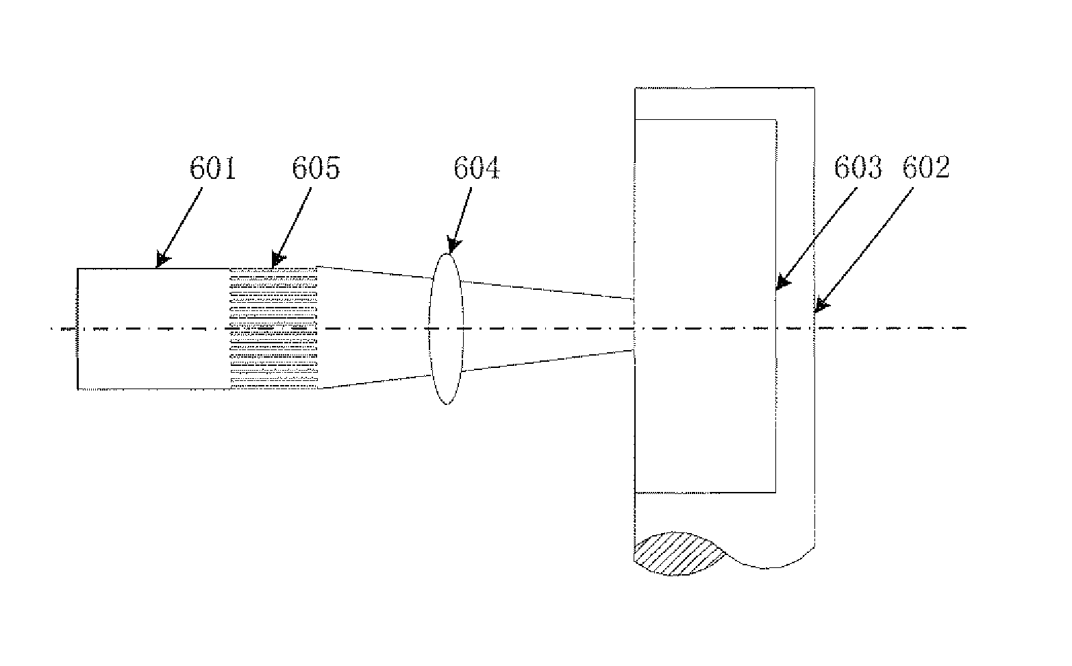
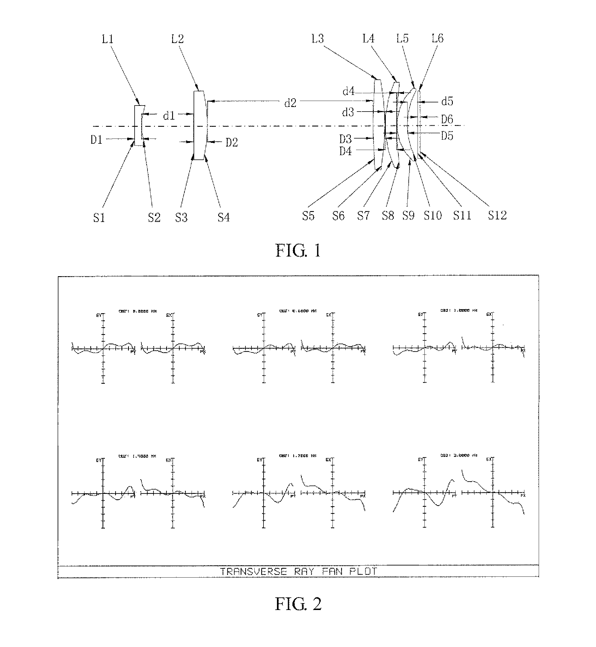
[0017]FIG. 1 is a schematic view of a near-infrared laser focusing lens according to an embodiment of the present invention. In order to facilitate illustration, FIG. 1 merely shows a portion of the near-infrared laser focusing lens associated with the embodiment.

[0018]The near-infrared laser focusing lens includes a first lens L1, a second lens L2, a third lens L3, a fourth lens L4 and a fifth lens L5 which are coaxially arranged along a transmission direction of the incident light beam. Th...


PUM


Abstract

A near-infrared laser focusing lens and a laser printing device are provided. The lens comprises a first lens, a second lens, a third lens, a fourth lens and a fifth lens (L1, L2, L3, L4, L5) which are coaxially arranged along a transmission direction of incident light rays, wherein the first lens (L1) is a negative plane-concave lens; the second lens and the third lens (L2, L3) are positive biconvex lenses; and the fourth lens and the fifth lens (L4, L5) are positive meniscus lenses; and a concave surface (S2) of the first lens (L1) is opposite to the second lens (L2), and the middle parts of the fourth lens and the fifth lens (L4, L5) both reversely protrude towards the transmission direction of light beams. After the shapes and the relative locations of the lenses are designed, the near infrared light can be clearly imaged, and the geometrical aberration of the lens can be effectively corrected, so as to obtain a clear flat field. In addition, because of having a large relative aperture and visual field and a long working distance, the lens is a microscope objective simultaneously having a large visual field, a large relative aperture, a long working distance and a flat field, and is capable of improving printing precision and clarity, so that the color rendition is truer and the operation is more convenient.

Description

FIELD OF THE INVENTION[0001]The present disclosure relates to a field of optical technology, and more particularly relates to a near-infrared laser focusing lens and a laser printing device.BACKGROUND OF THE INVENTION[0002]As the development of the laser processing technology, the laser printing technology is extensively applied to the fields of electronic composition, laser plate making and so on, greatly simplifying the printing technology. The digitization of the laser printing technology can realize a remote plate making and printing, thereby speeding up the press and publication, and also economizing the cost and human input on a large scale. The laser applied to the field of printing enables a rapid development of the printing industry.[0003]The realizing of the laser printing technology not only depends upon a widespread use of the fiber laser, but also profits from the continuously upgrading of parameters of the optical focusing system. The laser printing device generally ha...

Claims


Application Information

Patent Timeline
Patent Type & Authority Applications(United States)
IPC IPC(8): B41J2/455H01S3/02
CPCH01S3/02B41J2/455G02B9/60G02B13/14G02B13/24B41J2/442G02B13/18B41J2/435
Inventor LI, JIAYINGZHOU, CHAOMINGSUN, BOGAO, YUNFENG
Owner HANS LASER TECH IND GRP CO LTD
Why Eureka
Try Eureka