
VTOL aircraft with a thrust-to-weight ratio smaller than 0.1

a technology of thrust-to-weight ratio and aircraft, which is applied in the field of aircraft with vtol technology, can solve the problem that aircraft with thrust-to-weight ratio smaller than 0.1 cannot achieve vtol,

Inactive Publication Date: 2015-10-22
JING CHEN LI
View PDF11 Cites 2 Cited by
  • Summary
  • Abstract
  • Description
  • Claims
  • Application Information

AI Technical Summary

Benefits of technology

The patent describes a duct that helps to keep an aircraft's temperature low during vertical take-off and landing. This duct creates a low-temperature airflow that forms a thin layer on the surface of the aircraft, which helps to generate enough lift for the aircraft to overcome its weight and take off.

Problems solved by technology

Because of these limitations, VTOL is impossible for aircraft with thrust-to-weight ratio smaller than 0.1, and more particularly for large aircraft.

Method used


Image

  • VTOL aircraft with a thrust-to-weight ratio smaller than 0.1
  • VTOL aircraft with a thrust-to-weight ratio smaller than 0.1
  • VTOL aircraft with a thrust-to-weight ratio smaller than 0.1

Examples


Embodiment Construction

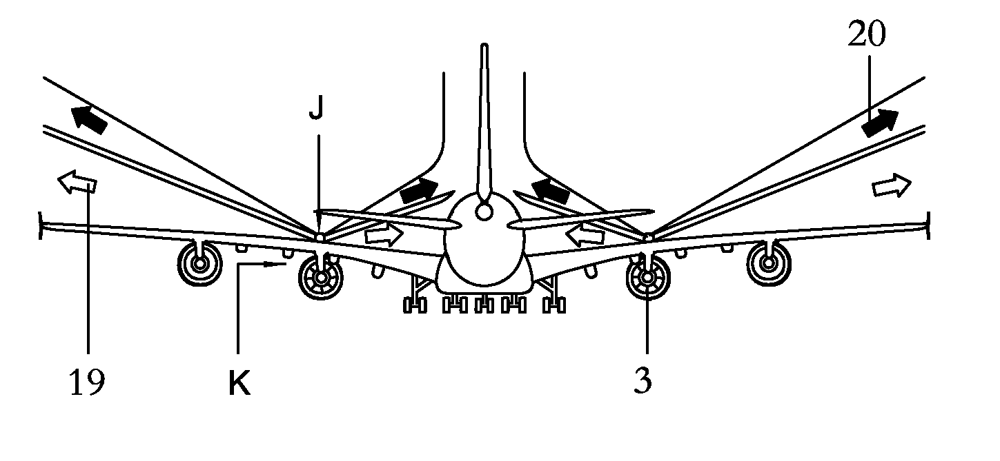
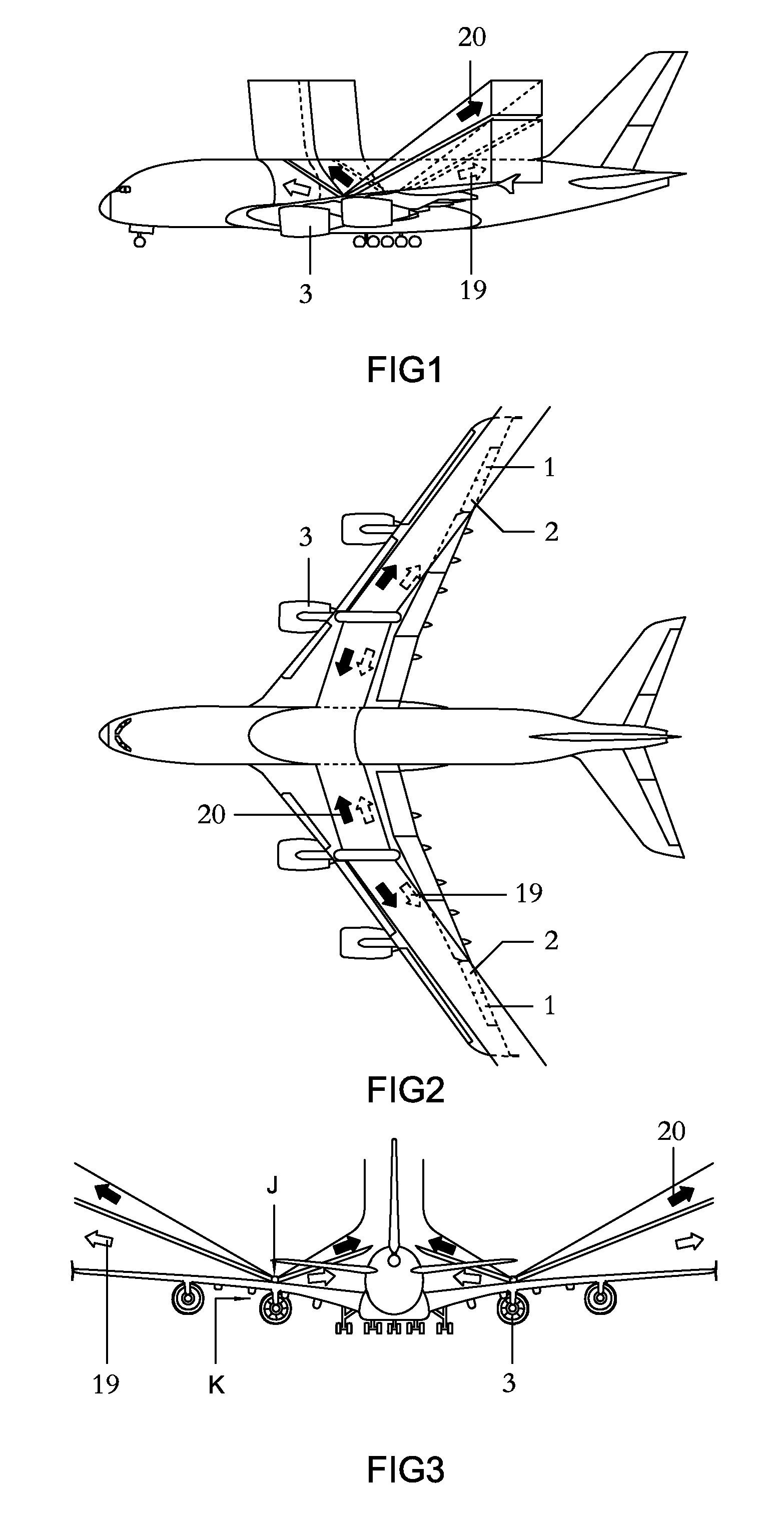
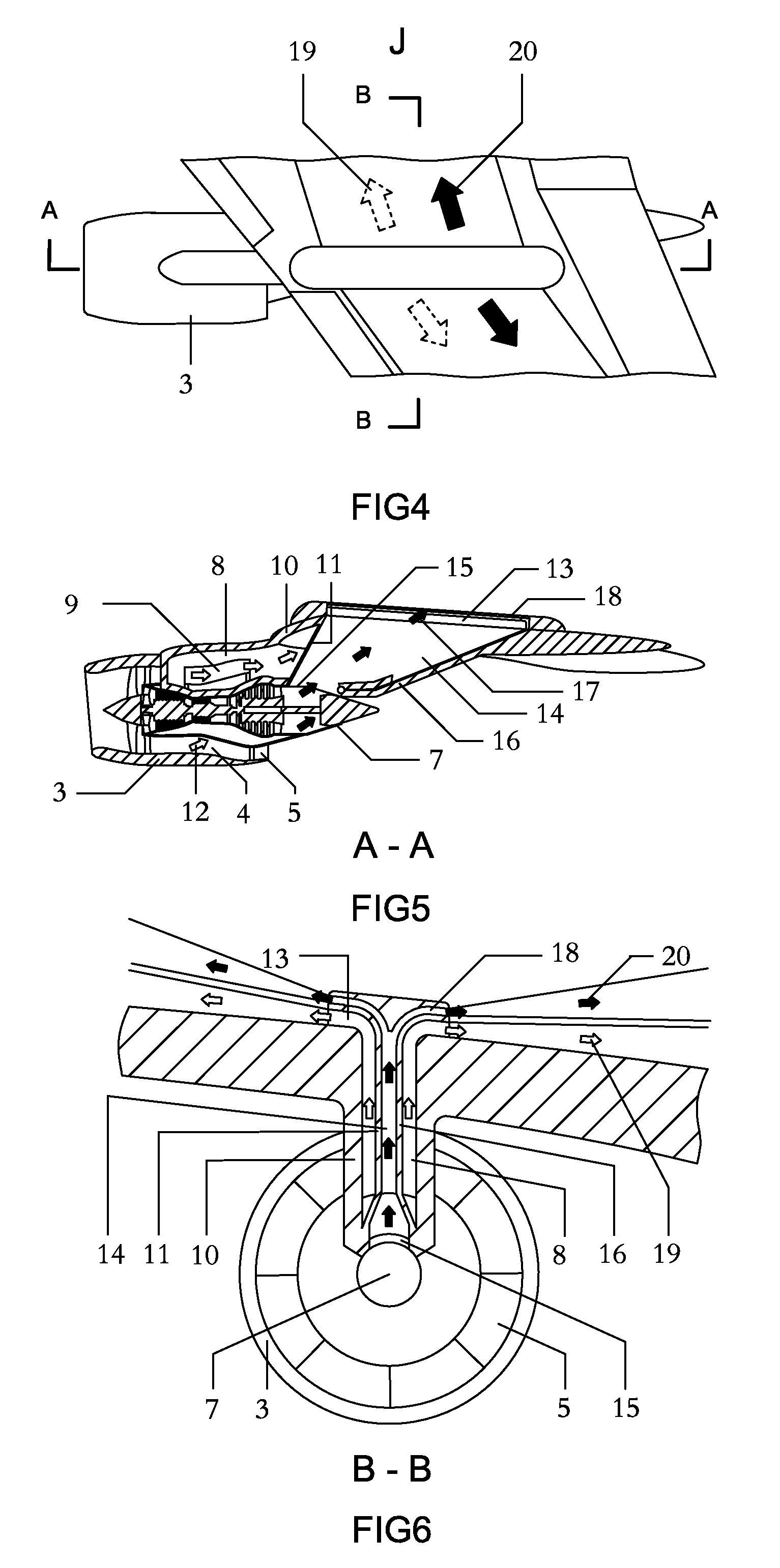
[0031]Referring to these drawings, the aircraft comprising: an aileron (1, 2) which one pair (1) rotate in opposite way and another pair (2) rotate in one way; a turbofan engine (3) comprising a low-temp duct (4) with an openable / closable propelling nozzle (5), and a high-temp duct (6) with an openable / closable propelling nozzle (7); a low-temp bypass duct (8) comprising an openable / closable inlet (9) connected to the low-temp duct (4), an outer wall (10) and an inner wall (11) which any cross-sectional area keeps low-temp airflow (12) less than velocity of sound, a rectangle outlet (13) with a height-to-width ratio smaller than 0.1; a high-temp bypass duct (14) comprising an openable / closable inlet (15) connected to the high-temp duct (6), an outer wall (16) Referring to these drawings, the aircraft comprising: an aileron (1, 2) which one pair (1) rotate in opposite way and another pair (2) rotate in one way; a turbofan engine (3) comprising a low-temp duct (4) with an openable / clo...


PUM


Abstract

VTOL aircraft with a thrust-to-weight ratio smaller than 0.1, during vertical take-off / landing, obtains another vertical lift, besides traditional vertical lift generated by low-temp bypass duct directing, under the closing of the propelling nozzle (7) of low-temp duct (6) of a turbofan engine and the opening of the inlet (14) of the low-temp bypass duct (15), the low-temp air (18) from the low-temp duct (6) to flow, in form of low-temp planar jet (20), over the upper surface of the wing along the wingspan, by high-temp bypass duct (15) directing, under the closing of the propelling nozzle (5) of high-temp duct (4) of the turbofan engine and the opening of the inlet (8) of the high-temp bypass duct (9), the high-temp air (18) from the high-temp duct (4) to flow, in form of high-temp planar jet (13), above the low-temp planar jet (20) but not burn up the wing along the wingspan and enables the ailerons (1, 2) to control the balances more efficiently.

Description

CROSS-REFERENCE TO RELATED APPLICATION[0001]This application is claims foreign priority benefit under 35 U.S.C. §119 of Patent Application EP 14075023.3 filed on 17 Apr., 2014, the contents of which are herein incorporated by reference.BACKGROUND OF THE INVENTION[0002]This invention relates to aircraft, and more particularly, to aircraft with VTOL technology.[0003]Currently, in the traditional VTOL technologies, thrust vectoring technology, such as AV-8, Yak-36 and F-35B, and additional lift engines, such as Yak-38 and Yak-141, in a least efficient way that air doesn't flow over the upper surface of the aircraft but rather over the lower one during vertical take-off / landing, get directly lift from reaction of atmosphere to air jet of jet engine; the use of tilt rotor, such as Boeing's V-22, and rotary wing, such as Boeing's X-50, in a little more efficient way that air both flow over the supper and lower of the aircraft during vertical take-off / landing, get lift from velocity differ...

Claims


Application Information

Patent Timeline
Patent Type & Authority Applications(United States)
IPC IPC(8): B64C29/00B64C23/00B64D27/16B64C9/00B64C15/02
CPCB64C29/00B64C9/00B64C2009/005B64D27/16B64C23/005B64C15/02B64C21/04B64C29/005B64C29/0066Y02T50/10
Inventor JING, CHEN LI
Owner JING CHEN LI
Learn More