
Land-mounted flap gate

Active Publication Date: 2015-10-22
HITACHI ZOSEN CORP
View PDF0 Cites 1 Cited by
  • Summary
  • Abstract
  • Description
  • Claims
  • Application Information

AI Technical Summary

Benefits of technology

The present invention aims to improve the installation and maintenance of doors by introducing a mechanism that helps to generate additional force for the operation of each door. This mechanism reduces the burden of maintenance and repair because it does not require the removal of waterproof films when performing inspections on the start of raising or between the lowered state and the raised state.

Problems solved by technology

Problems that the present invention attempts to solve reside in that, in the case where a floating body-type flap gate is installed on the top surface of the embankment of a seawall or the like, when a floating body-type flap gate is introduced as flooding prevention means for a long-span opening, a scheme for generating sufficient auxiliary force to the operations of door bodies using only both sides of the floating body-type flap gate imposes limitations on the width of a gate to be installed in terms of structure and also it is very cumbersome to perform a floating inspection on the start of raising.

Method used


Image

  • Land-mounted flap gate
  • Land-mounted flap gate
  • Land-mounted flap gate

Examples


embodiment

[0031]Hereinafter, an embodiment for carrying out the present invention is explained in detail with reference to FIGS. 1 to 5.

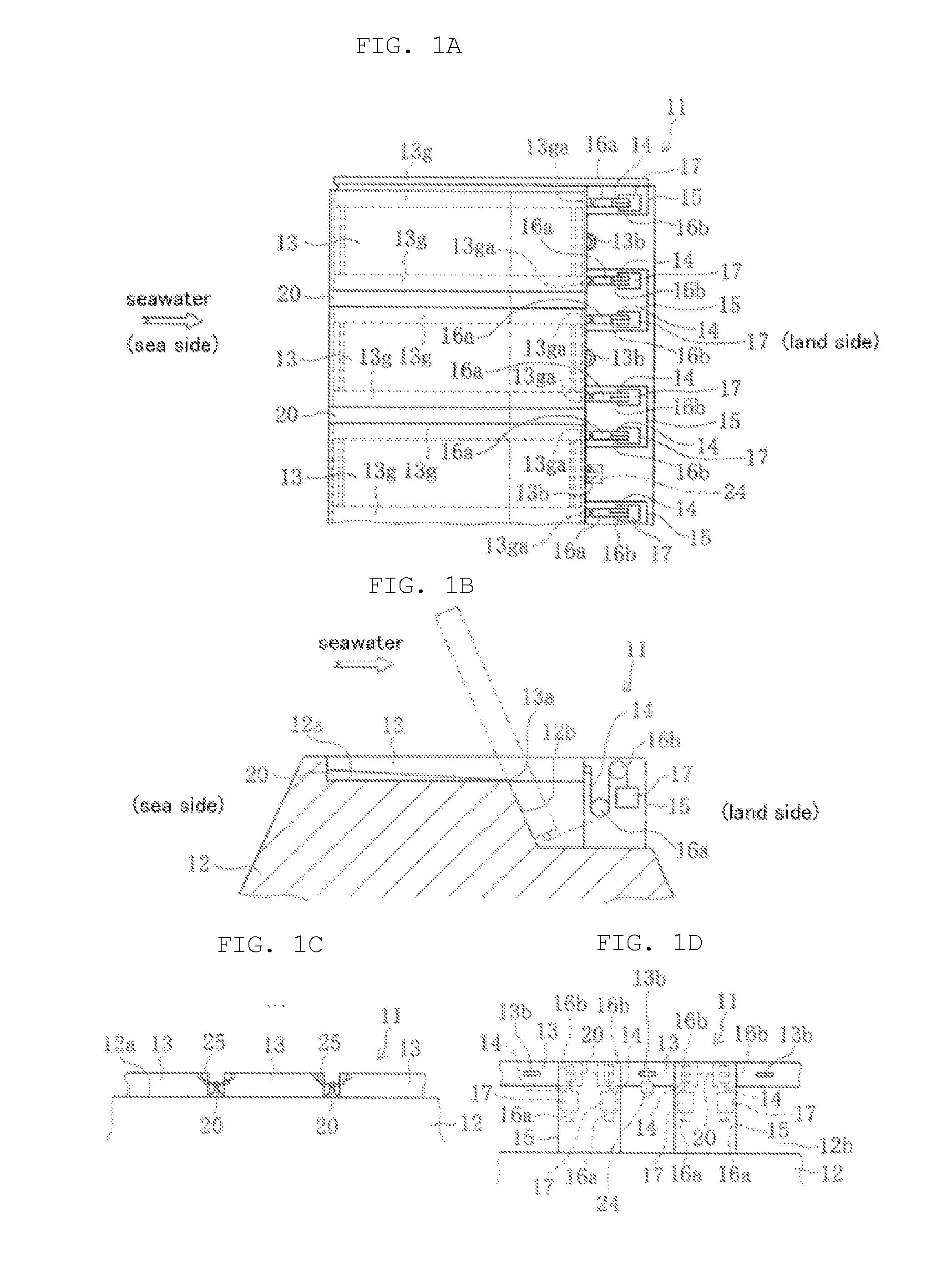
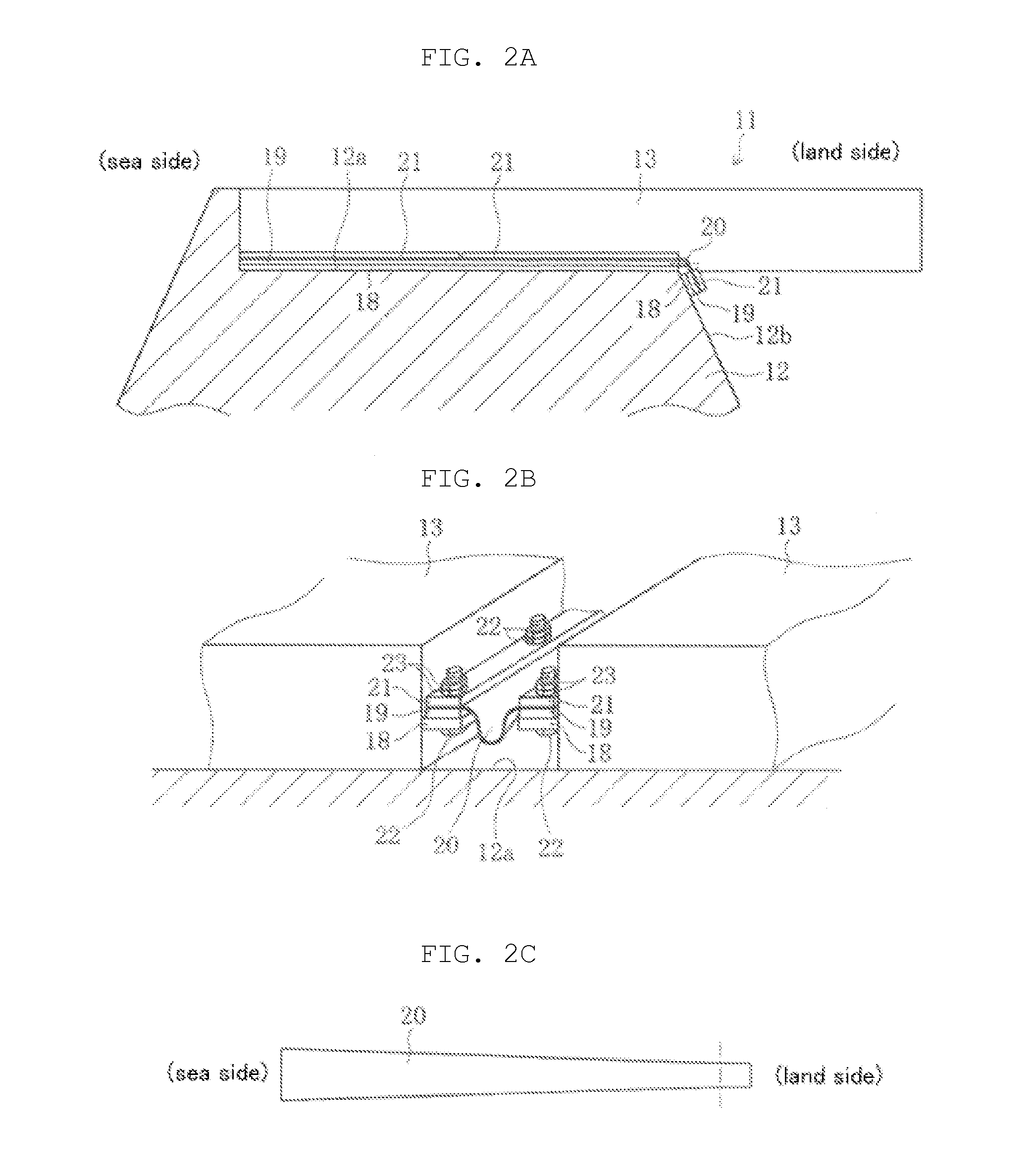
[0032]FIGS. 1A-1D illustrate views of the schematic configuration of a land-mounted flap gate according to an embodiment of the present invention.

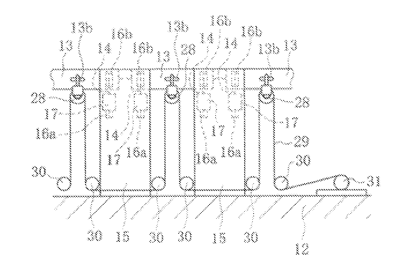
[0033]In FIGS. 1A-1D, reference numeral 11 denotes the land-mounted flap gate of the present embodiment installed on the top surface 12a of the embankment of a seawall 12. The land-mounted flap gate 11 is raised by sea water flowing over the seawall 12 when high tides or tidal waves occur, and then prevents sea water from flowing from the seawall 12 into a land side. In FIGS. 1A and 1B, a left side falls under a sea side and a right side falls under a land side.

[0034]The land-mounted flap gate 11 is formed by arranging and connecting a plurality of door bodies 13 alongside one another, as illustrated in FIG. 1A. As illustrated by imaginary lines (dotted lines) in FIG. 1B, the front side of the land-mounted flap gate...


PUM


Abstract

A land-mounted flap gate formed by arranging and connecting a plurality of door bodies alongside one another is disclosed. The front side of each of the plurality of door bodies is raised and lowered using the back end side of each door body as a support point. One end of a rope is attached to the back end surface of the door body and the other end of the rope is attached to a counter weight. At least one fixed pulley for guiding the rope is disposed below the back end side of the door body such that the counter weight assists the raising or lowering when starting the raising or lowering and acts as a resistance against the raising or lowering before completing the raising or lowering. The waterproof film that seals a space between neighboring door bodies in a waterproof manner is formed in a substantially trapezoidal shape.

Description

CROSS-REFERENCES TO RELATED APPLICATIONS[0001]This patent specification is based on Japanese patent application, No. 2014-084526 filed on Apr. 16, 2014 in the Japan Patent Office, the entire contents of which are incorporated by reference herein.BACKGROUND OF THE INVENTION[0002]1. Field of the Invention[0003]The present invention relates to a land-mounted flap gate that is installed in a wide-span opening such as the top surface of the embankment of a seawall or the like as a countermeasure against, for example, high tides or tidal waves.[0004]2. Description of Related Art[0005]An example of a flap gate is a floating body-type flap gate that is installed in an opening of a seawall and that raises door bodies using the buoyancy of incoming water to block the opening in order to prevent water increased at the time of water increase from flowing into living spaces or underground spaces (see, e.g., Japanese Unexamined Patent Application Publication No. 2012-241449).[0006]When such a flo...

Claims


Application Information

Patent Timeline
IPC IPC(8): E02B3/04E02B3/12E02B3/06
CPCE02B3/04E02B3/12E02B3/062E02B3/16E02B3/102E02B7/20E02B7/54
Inventor NAKAYASU, KYOUICHIKIMURA, YUUICHIROYOSHIKI, RYOUTAMORII, TOSHIAKI
Owner HITACHI ZOSEN CORP
Features
  • Generate Ideas
  • Intellectual Property
  • Life Sciences
  • Materials
  • Tech Scout
  • Unparalleled Data Quality
  • Higher Quality Content
  • 60% Fewer Hallucinations
Learn More