Electromagnetic clutch, electromagnetic clutch control device, and electromagnetic clutch control method

Inactive Publication Date: 2015-10-22
DENSO CORP
View PDF7 Cites 5 Cited by
  • Summary
  • Abstract
  • Description
  • Claims
  • Application Information

AI Technical Summary

Benefits of technology

The present invention aims to provide an electromagnetic clutch with improved starting performance and minimized power consumption. It improves operability by generating a stronger electromagnetic attraction force between the rotor and the armature when power is first supplied to the electromagnetic coil. This is achieved by increasing the number of opposing magnetic paths between the rotor and the armature, and minimizing power consumption of the electromagnetic coil by reducing the magnetomotive force of the coil. The invention returns the magnetomotive force of the electromagnetic coil to a normal state after magnetically attracting and fixing the armature to the friction plate, thereby minimizing power consumption.

Problems solved by technology

Consequently, an electromagnetic attraction force when power is first supplied to the electromagnetic coil, that is, an actuation attraction force for switching the electromagnetic clutch from an off state to an on state becomes weaker, thereby causing a possibility of the operability (starting performance) of the electromagnetic clutch degrading.

Method used


Image

  • Electromagnetic clutch, electromagnetic clutch control device, and electromagnetic clutch control method
  • Electromagnetic clutch, electromagnetic clutch control device, and electromagnetic clutch control method
  • Electromagnetic clutch, electromagnetic clutch control device, and electromagnetic clutch control method

Examples


Embodiment Construction

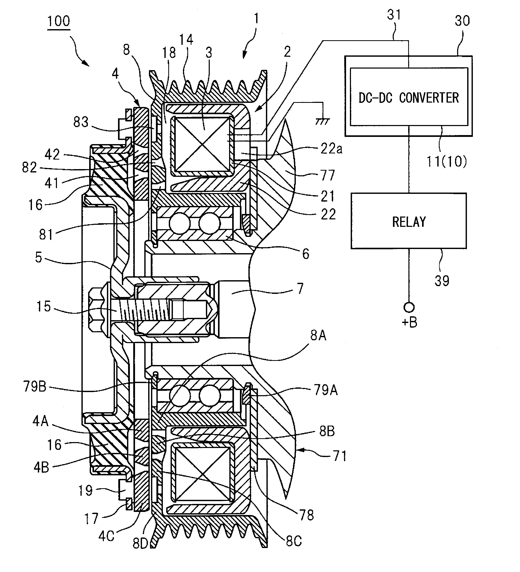
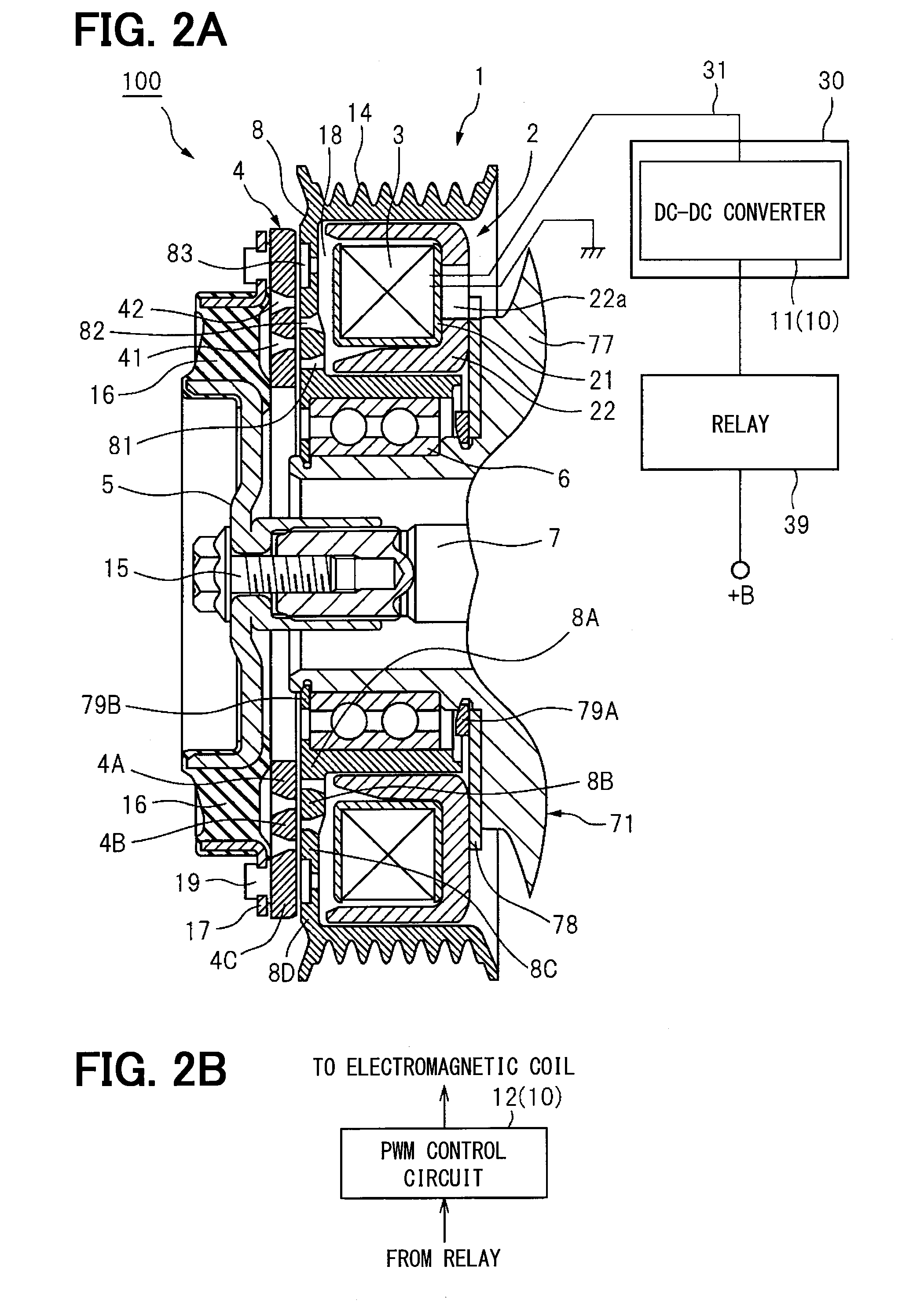
[0030]Hereinafter, embodiments of an electromagnetic clutch according to the present disclosure will be described based on specific examples with reference to the drawings. Here, as an example, an embodiment will be described where the electromagnetic clutch according to the present disclosure is attached to a vehicle auxiliary machine. In some cases, repeated description in each embodiment will be omitted by giving the same reference numerals to portions corresponding to elements described previously. When only a portion of configurations in each example is described, another embodiment described previously can be applied to the other portions of the configurations. Portions described as that a specific combination is possible in respective examples can be combined with each other. Moreover, if no problems particularly occur in the combination, the respective examples can also be partially combined with each other without being described.

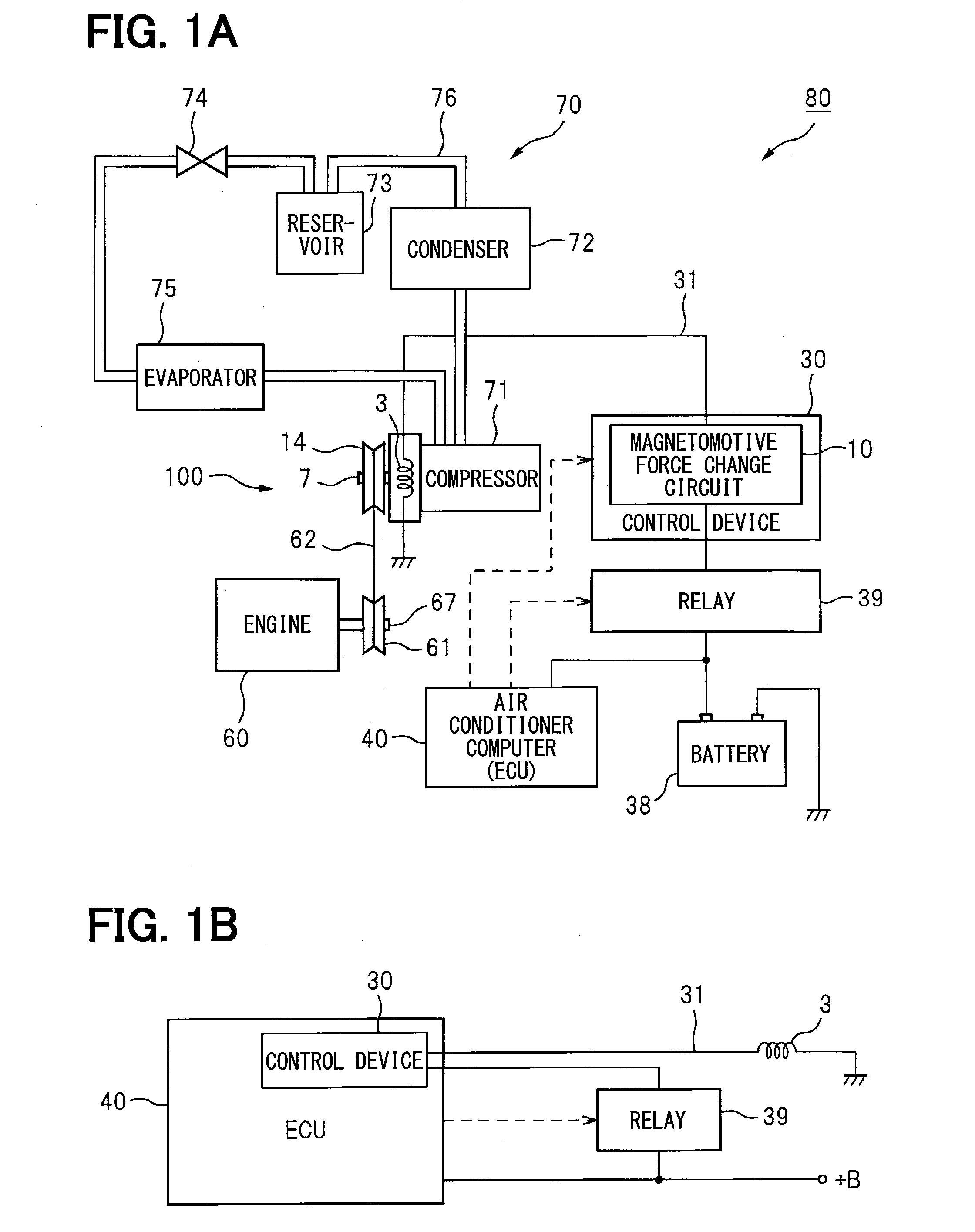
[0031]FIG. 1A illustrates an example of a co...


PUM


Abstract

An electromagnetic clutch provided with an armature in which two or more non-magnetic sections of differing radii are provided and which is installed on a rotary shaft, a rotor in which three or more non-magnetic section of differing radii that do not overlap with the non-magnetic sections are provided on a friction plate that faces the armature, and which rotates with respect to the rotation shaft by external force, a stator equipped with an electromagnetic coil for fixing the armature to the rotor by applying magnetic flux, which is generated by passage of an electric current, on the friction plate, and a control device for the electromagnetic coil. The control device is provided with a magnetomotive force change circuit for increasing, with a command to start power supply to the electromagnetic coil, the magnetomotive force of the electromagnetic coil above the magnetomotive force of the electromagnetic clutch during normal operation and for returning the magnetomotive force of the electromagnetic coil to the magnetomotive force of the electromagnetic clutch during normal operation when the armature is fixed to the rotor.

Description

CROSS-REFERENCE TO RELATED APPLICATION[0001]The present application is based on Japanese patent application No. 2012-246086 filed on Nov. 8, 2012, the content of which is incorporated herein by reference.TECHNICAL FIELD[0002]The present disclosure relates to an electromagnetic clutch, an electromagnetic clutch control device, and an electromagnetic clutch control method for intermittently transmitting power using an electromagnet.BACKGROUND ART[0003]In a drive mechanism of a compressor for a vehicle air conditioner and the like, an electromagnetic clutch is used when power is intermittently transmitted using an electromagnetic coil. An armature is fixed to a distal end portion of a rotary shaft of the compressor. A rotor driven by an engine or the like is attached to the rotary shaft adjacent to the armature via a bearing, and is rotatable with respect to the rotary shaft. The rotor has a recess formed in a ring shape extending from the compressor side, and a stator including the el...

Claims


Application Information

Patent Timeline
IPC IPC(8): F16D48/06F16D27/112
CPCF16D27/112F16D48/064F16D2500/1022F16D2500/5108F16D2500/5114F16D2500/70418F16D2500/7042F16D2500/7109
Inventor UEDA, MOTOHIKOOOKUMA, TOORU
Owner DENSO CORP
Why Eureka
Try Eureka