

Valve Seat for Floating Ball Valve
- Summary
- Abstract
- Description
- Claims
- Application Information
AI Technical Summary
Benefits of technology
Problems solved by technology
Method used
Image

Examples
Embodiment Construction
[0025]A valve seat in a specific embodiment of the present invention is described in detail with reference to the accompanying drawings. However, it should be understood that, the present invention is not limited to the described embodiment, and technical ideas of the present invention can be implemented in combination with other well-known technologies or other technologies having functions the same as those of the well-known technologies.
[0026]In the following description, in order to clearly show the structure and working manner of the present invention, many directional terms are used; however, it should be understood that, those words such as “front”, “back”, “left”, “right”, “inner”, “outer”, “outwards”, “inwards”, “axial”, and “radial” are only used for ease of illustration instead of limiting the present invention.
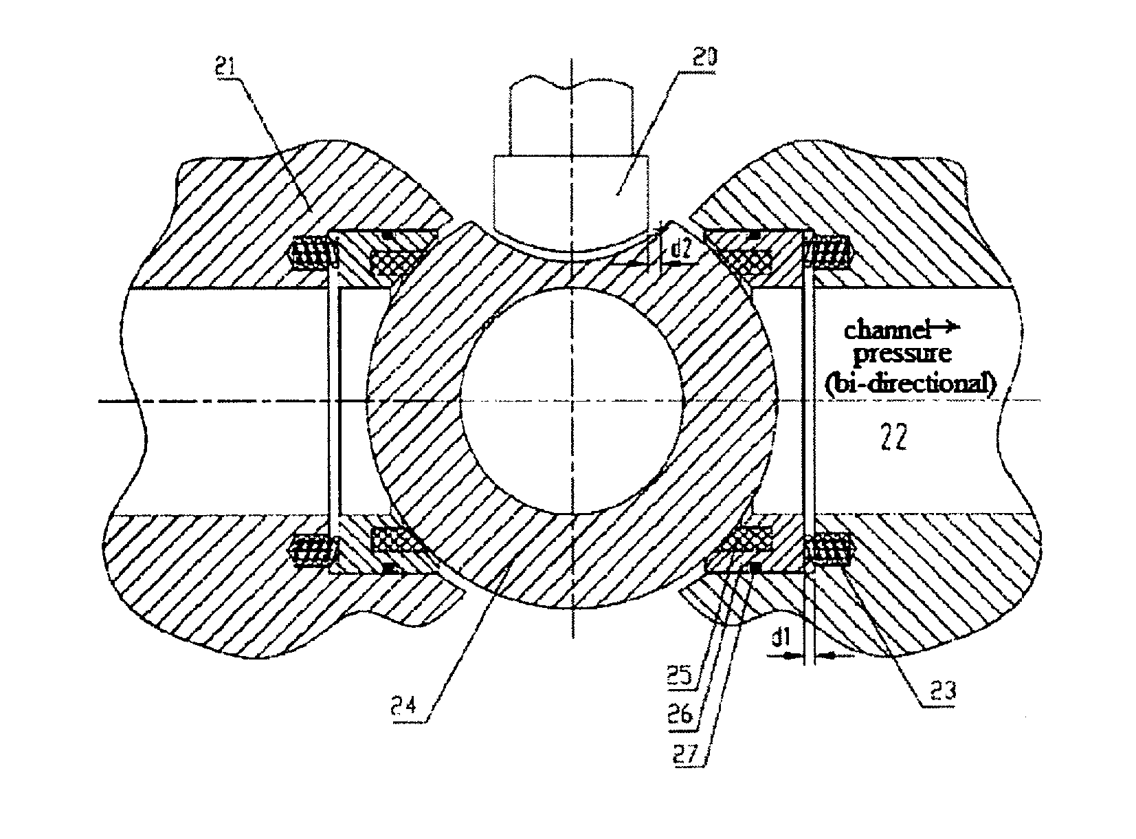
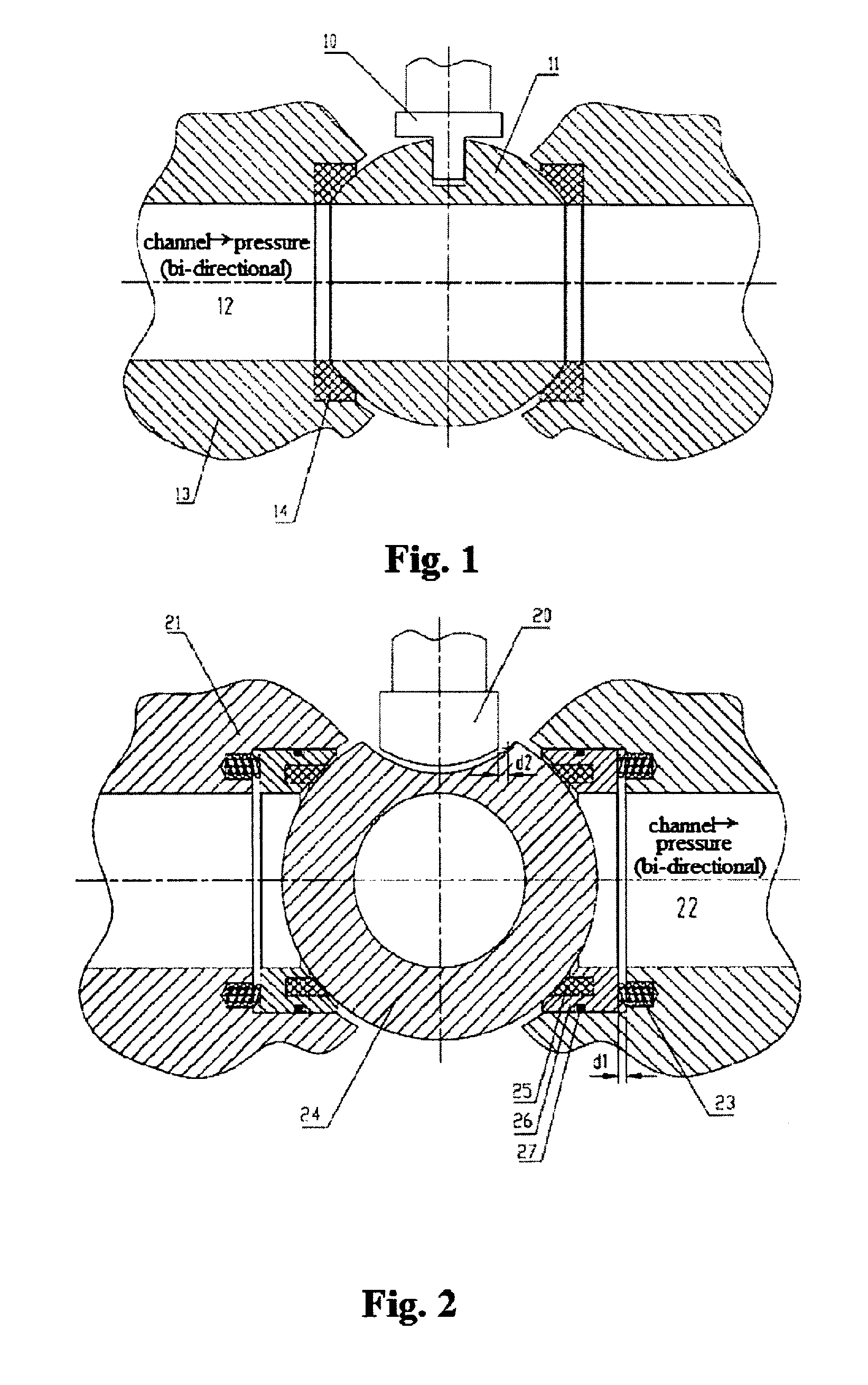
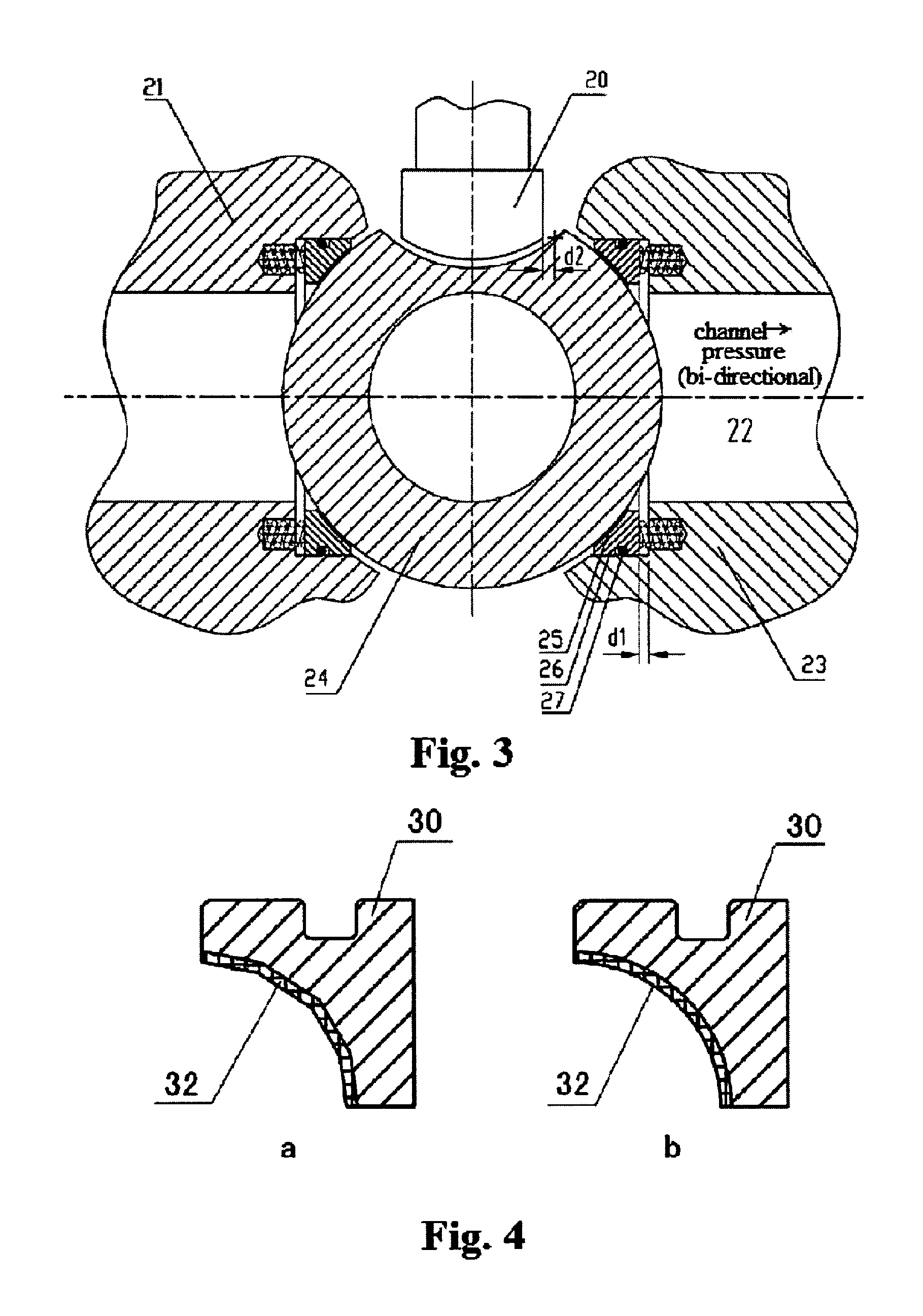
[0027]FIG. 1 shows an open state of a floating ball valve in the prior art, where 10 represents a valve stem, 11 represents a ball, 12 represents a media channel, ...
PUM
 Abstract
Description
Claims
Application Information