Device and method for measuring flow rate of steel melt near the surface thereof

Active Publication Date: 2015-10-22
BAOSHAN IRON & STEEL CO LTD
View PDF2 Cites 2 Cited by
  • Summary
  • Abstract
  • Description
  • Claims
  • Application Information

AI Technical Summary

Benefits of technology

The invention provides a device and method for measuring the flow rate of steel melt near the surface thereof with high precision, reliability, and low cost. The device includes a flow rate detecting rod and a counterweight to achieve gravity balance, which maximizes the rotational sensitivity of the flow rate detecting rod. The measurement method is simple and requires only one replacement of the flow rate detecting rod. The device and method have advantages such as high measurement precision, reliable measurement results, simple measurement operation, low measurement cost, etc.

Problems solved by technology

Due to the high temperature up to about 1600° C. of steel melt, the devices and methods commonly used for measuring liquid flow rates do not work.
Hence, measurement of the actual flow rate of high-temperature steel melt becomes a difficult technical problem in the field of steel making.
If the engulfment and mixing of the mold flux occurs, surface flaws of the cold rolled steel plate will be incurred, and thus the product yield will be decreased.
As a result, the temperature of the steel melt at the meniscus will decrease, and thus the mold flux will not be melted sufficiently, such that the function of the mold flux for capturing floating inclusions will be degraded.
Instead, the inclusions and mold flux are captured at the solidified shell 7 near the meniscus, which also leads to increased occurrence of flaws in the final product of cold rolled strip.
Unfortunately, the device used in this measurement method is rather complicated.
Moreover, the harsh high-temperature environment also influences the precision and stability of the pressure sensor in operation, leading to large error in flow rate measurement.
Hence, the sensitivity of the flow rate measurement is not good.
As the flow rate detecting rod is cheap, the cost of the flow rate measurement is low.

Method used


Image

  • Device and method for measuring flow rate of steel melt near the surface thereof
  • Device and method for measuring flow rate of steel melt near the surface thereof
  • Device and method for measuring flow rate of steel melt near the surface thereof

Examples


Embodiment Construction

[0032]The technical solution of the invention will be further illustrated with reference to the accompanying drawings and examples.

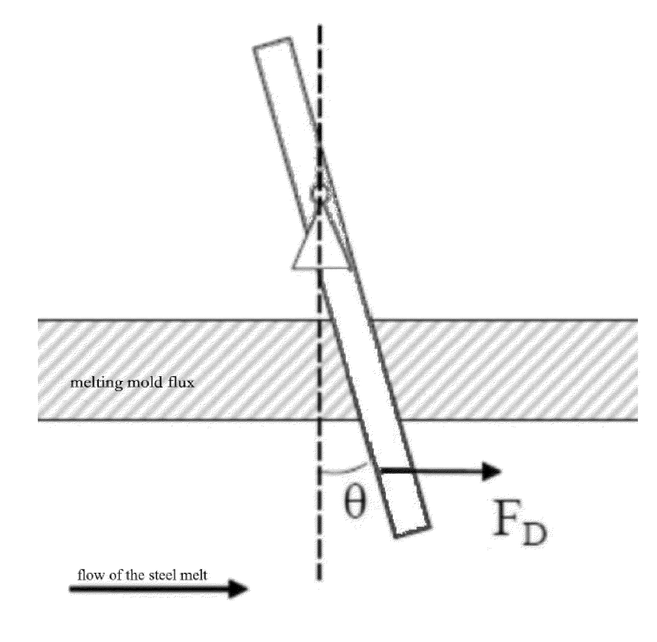
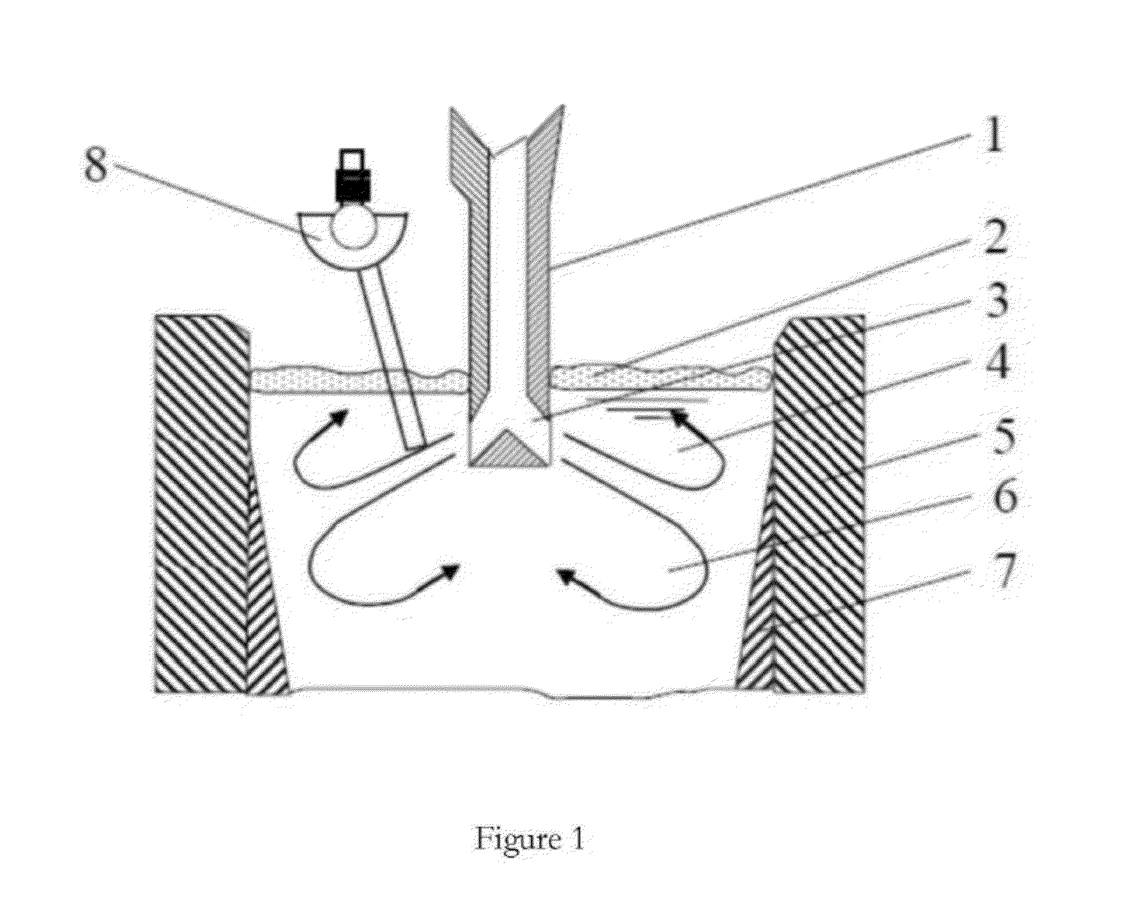
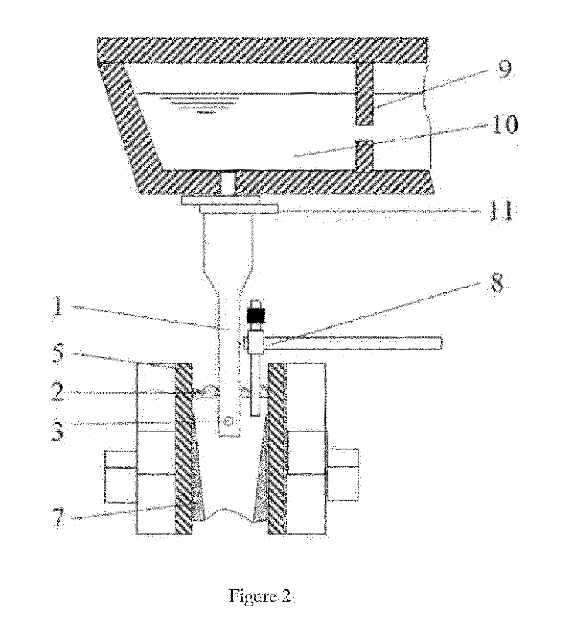
[0033]The invention relates to a device and a method for measuring the flow rate of steel melt near the surface thereof, particularly for measuring the flow rate of steel melt near the surface thereof in a crystallizer. Direct measurement of the flow rate of steel melt near the surface thereof in a crystallizer allows control over the flow field of the steel melt in the crystallizer, so as to reduce effectively the surface flaws of a continuous casting blank caused by entrapped mold flux, inclusions, bubbles and the like, which, in turn, reduces the occurrence of the surface flaws of a cold rolled plate such as an automobile shell plate, etc.

[0034]The flow field of the steel melt in the crystallizer or tundish is of great significance for controlling inclusions in a casting blank and the surface quality of the casting blank in steel making. Due to the hi...


PUM

PropertyMeasurementUnit
Angleaaaaaaaaaa
Flow rateaaaaaaaaaa
Gravityaaaaaaaaaa

Abstract

A device for measuring the flow rate of steel melt near the surface thereof. The device has a flow rate detecting rod and a deflection device for the flow rate detecting rod. The deflection device for the flow rate detecting rod has a flow rate detecting rod counterweight, a deflection bearing sleeve, a deflection bearing, a deflection angle indicating board, a deflection angle pointer and a the flow rate detecting rod fastening bolt.

Description

TECHNICAL FIELD[0001]The invention relates to a device and a method for measuring a flow parameter of high-temperature steel melt, more particularly to a device and a method for measuring the flow rate of steel melt near its surface.BACKGROUND ART[0002]The flow field of the steel melt in the crystallizer or tundish is of great significance for the controlling over inclusions and casting blank quality in the process of steel making. Due to the high temperature up to about 1600° C. of steel melt, the devices and methods commonly used for measuring liquid flow rates do not work. Hence, measurement of the actual flow rate of high-temperature steel melt becomes a difficult technical problem in the field of steel making.[0003]Direct measurement of the flow rate of steel melt near the surface thereof in a crystallizer allows control over the flow field of the steel melt in the crystallizer, so as to reduce effectively the surface flaws of a continuous casting blank caused by entrapped mold...

Claims


Application Information

Patent Timeline
IPC IPC(8): G01F1/28G01P5/04
CPCG01P5/04G01F1/28B22D2/00B22D11/041B22D11/16
Inventor YANG, JIANZHI, JIANJUNZHU, KAIZHU, JIANHUAFAN, ZHENGJIEWANG, RUIZHISHEN, JIANGUOZHENG, YIYU
Owner BAOSHAN IRON & STEEL CO LTD
Why Eureka
Try Eureka