Piezoelectric or electret sensing device

Active Publication Date: 2015-10-22
IEE INT ELECTRONICS & ENG SA
View PDF6 Cites 5 Cited by
  • Summary
  • Abstract
  • Description
  • Claims
  • Application Information

AI Technical Summary

Benefits of technology

[0007]As will be appreciated, the piezoelectric and/or electret transducer and the waveform generator (which may e.g. comprise an oscillator and/or a pseudo-random noise generator) are connected electrically in series between the first input and the second input of the transimpedance amplifier. The waveform generator produces its waveform in

Problems solved by technology

As a disadvantage of the disclosed system, the measurement mode

Method used


Image

  • Piezoelectric or electret sensing device
  • Piezoelectric or electret sensing device
  • Piezoelectric or electret sensing device

Examples


Example

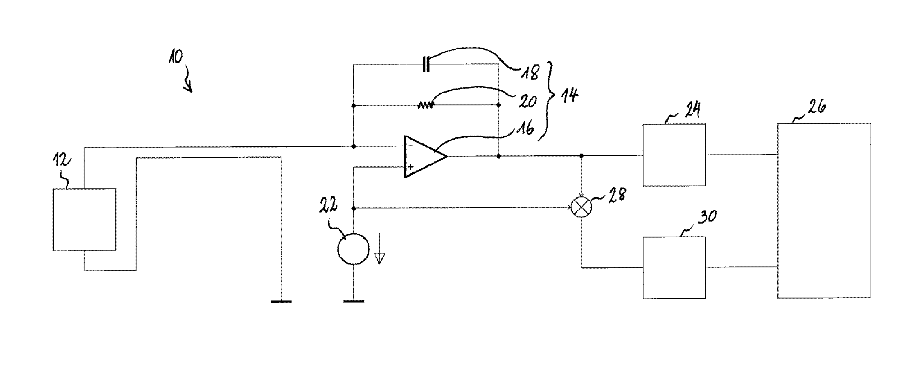
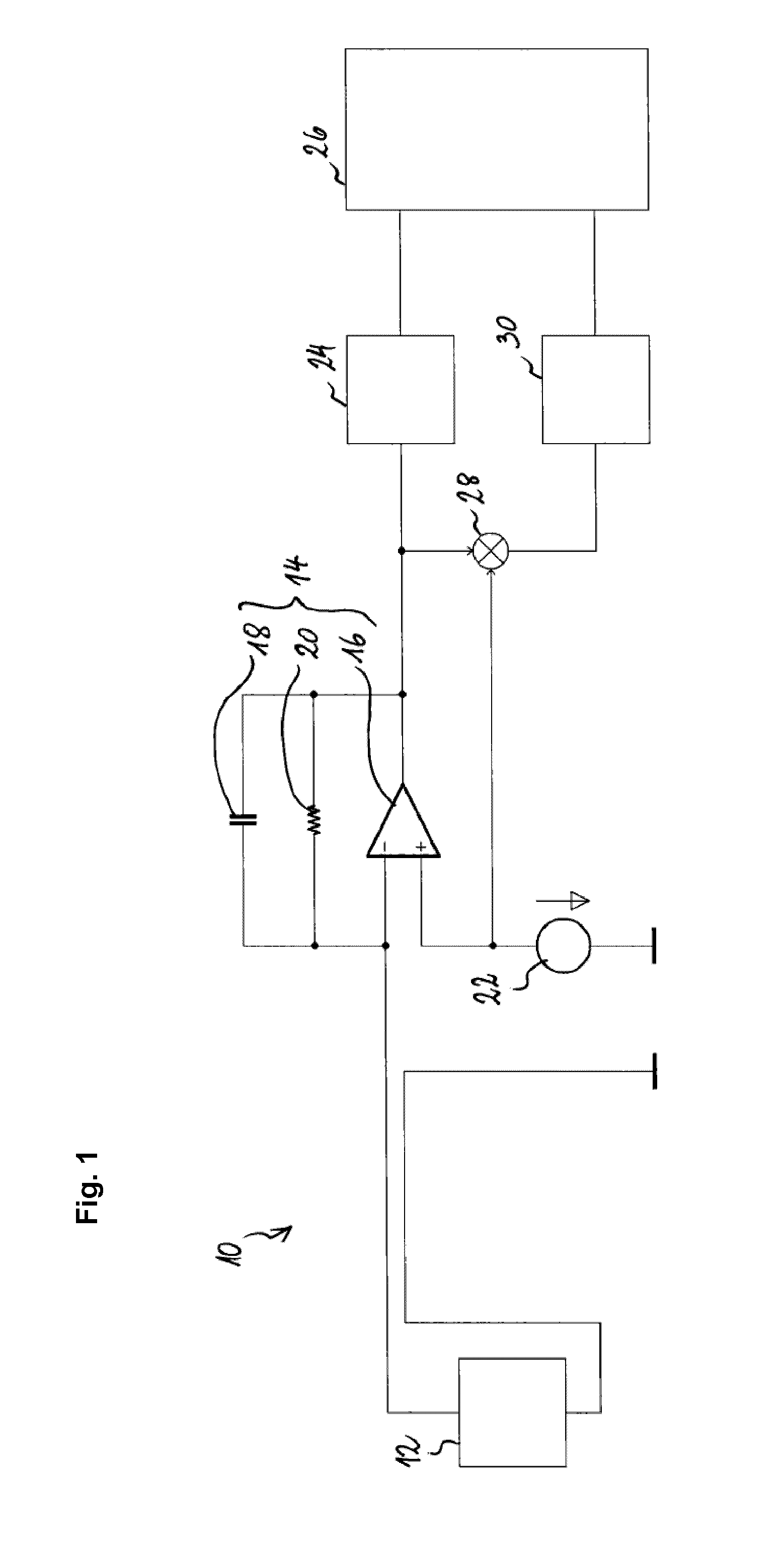
[0019]FIG. 1 shows a piezoelectric sensing device 10 according to a first preferred embodiment of the invention. The piezoelectric sensing device 10 comprises a piezoelectric transducer 12 that produces a current (referred to herein as the “measurement current”) in response to a mechanical stimulus (vibration, movement, strain or the like). The transducer 12 is connected between ground and the first input of a transimpedance amplifier 14. The transimpedance amplifier 14 (depicted as including an operational amplifier 16 and a feedback network with a capacitor 18 and a resistor 20) converts the current from the transducer 12 into a corresponding voltage on the output terminal of the transimpedance amplifier 14. The second input (reference input) of the transimpedance amplifier 14 is connected to a diagnostics signal source 22, which applies a variable voltage signal (electrical waveform) to the second input. The transimpedance amplifier 14 attempts to maintain a zero voltage differen...


PUM


Abstract

A piezoelectric and/or electret sensing device (10) comprises a piezoelectric and/or electret transducer (12) for producing a measurement current in response to mechanical stimulus, and a control and evaluation circuit connected to the transducer. The control and evaluation circuit (14, 24, 26, 28, 30) comprises a transimpedance amplifier (14) having a first and a second input, the transducer being operatively connected between the first input and a reference node, and an electrical waveform generator (22) for generating an electrical waveform, the electrical waveform generator being operatively connected between the second input and the reference node. The transimpedance amplifier controls the first input such that the difference in electric potential between the first input and the second input be cancelled and outputs an output voltage indicative of electrical current flowing across the transducer. The control and evaluation circuit identifies a first component of the output voltage indicative of the measurement current and a second component of the output voltage indicative of the current caused by the generation of the waveform and detects a short circuit and/or a broken wire based upon the second component.

Description

TECHNICAL FIELD[0001]The present invention generally relates to piezoelectric or electret sensors, which may e.g. be used for detecting vibration or displacement. More specifically, the present invention relates to diagnostics of such sensors.BACKGROUND ART[0002]Piezoelectric or electret transducers are well known as such. They are typically used to convert a mechanical stimulus (such as vibration, movement, strain etc.) into an electrical signal.[0003]US patent application 2010 / 0295563 A1 discloses an occupant detection system with an electrode arrangement for a seat of an automotive vehicle, wherein the electrode arrangement includes a first electrode, a second electrode and an electric insulator layer sandwiched between the first and second electrodes. When the electrode arrangement is in place in the seat, the first electrode forms with vehicle ground a first capacitor having a first capacitance influenceable by an occupying item in the detection region through interaction of th...

Claims


Application Information

Patent Timeline
IPC IPC(8): G01R31/28H01L41/113G01R31/02G01H11/08G01R31/50
CPCG01R31/2829G01R31/02H01L41/1132G01H11/08G01R29/22B60R25/00G01R31/50H10N30/302
Inventor LAMESCH, LAURENT
Owner IEE INT ELECTRONICS & ENG SA
Why Eureka
Try Eureka