Plasma device

a technology of plasma and arc discharge, which is applied in the direction of plasma technique, gas-filled discharge tubes, solid cathodes, etc., can solve the problems of inability to simultaneously produce a large area arc discharge, speed of plasma treatment may be raised, and the application of this type of atmospheric arc plasma is still limited, so as to achieve favorable reliability and performance, and large area surface treatment

Active Publication Date: 2015-10-22
CREATING NANO TECH INC
View PDF4 Cites 8 Cited by
  • Summary
  • Abstract
  • Description
  • Claims
  • Application Information

AI Technical Summary

Benefits of technology

[0007]The invention is directed to a plasma device capable of performing a large area surface treatment and having favorable reliability and performance.
[0020]In view of the foregoing, the plasma device of the invention, by separately disposing an independent gas ejection port beside the nozzle of the rotatable plasma, in addition to achieving a high performance of a large area surface treatment effect, may also timely introduce airflow to cool down the object being treated, even if it is a heat sensitive object, and may further effectively lower a surface temperature of the object being treated, so that the object being treated can undergo a high performance plasma surface treatment within a short time, thereby enabling the high performance plasma surface treatment not to be limited and influenced by the material of the object being treated.

Problems solved by technology

However, as being restricted by negative resistance characteristics of an electric arc, a process range of this type of atmospheric arc plasma is limited, and thus is unable to simultaneously produce a large area arc discharge.
Although a discharge density of the atmospheric arc plasma is relatively higher and causes more active substances to be produced by this plasma technique, so that a speed of the plasma treatment may be raised (it requires only a short amount of time to complete the surface treatment for a scanning area), large area arc discharge characteristic is unable to be produced, and thus the application of this type of atmospheric arc plasma is still being limited.
However, as high power is being applied, a temperature of the plasma also rises and thereby influences the performance of the plasma in performing the surface treatment to the object being treated, especially for heat sensitive objects, such as flexible substrate and so forth.
Therefore, how to retain the performance of the plasma treatment while controlling the temperature of a substrate is one of the issues that have to be conquered in the field of plasma device.
Moreover, in addition to the problem of unable to effectively lower the temperature of the plasma, a rod-shaped inner electrode as disclosed by U.S. Pat. No. 6,262,386 is also apt to be damaged due to the plasma being concentrated on a single point, especially when high power is being applied, and thereby influences a reliability of the device.

Method used


Image

  • Plasma device
  • Plasma device
  • Plasma device

Examples


Embodiment Construction

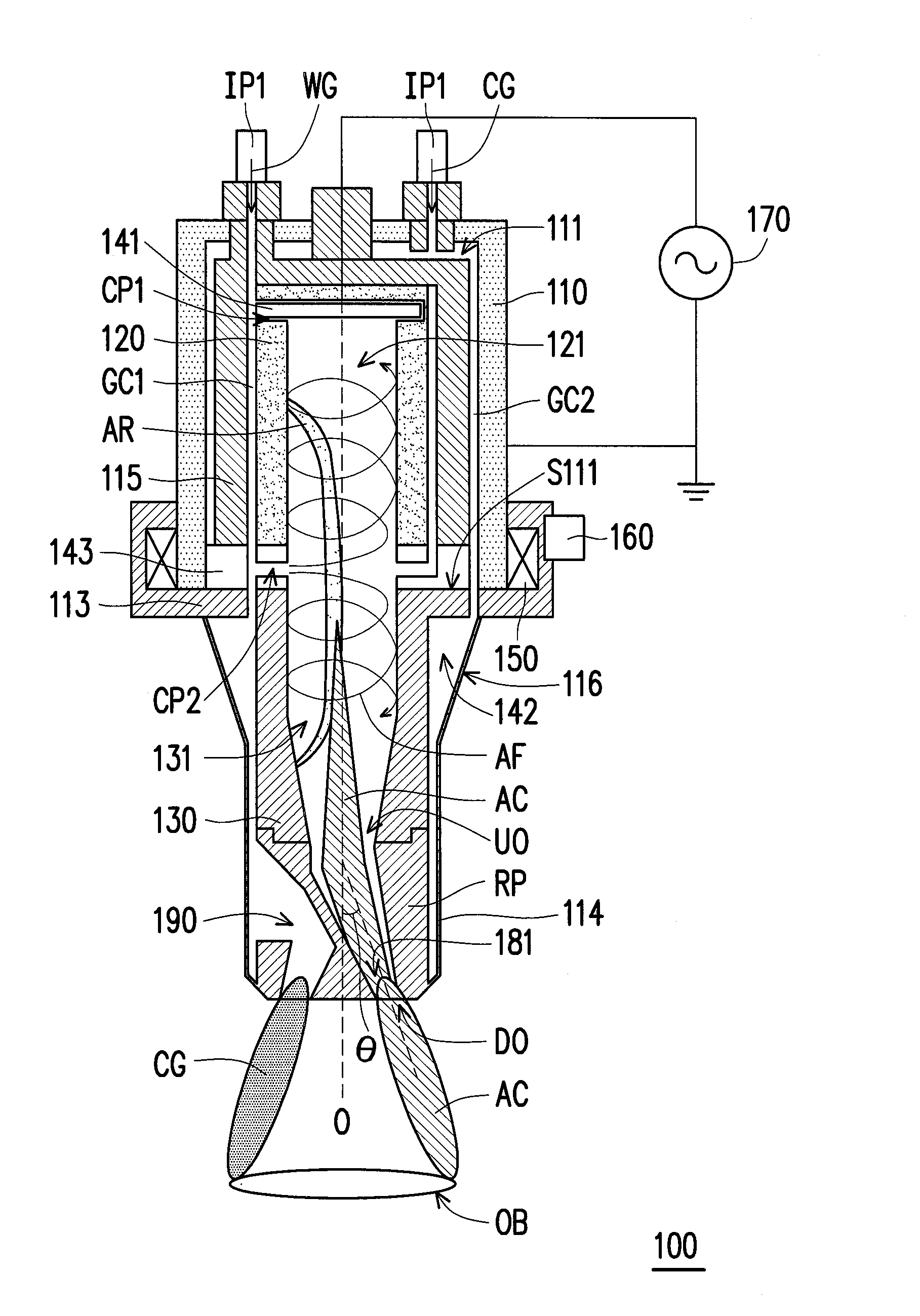
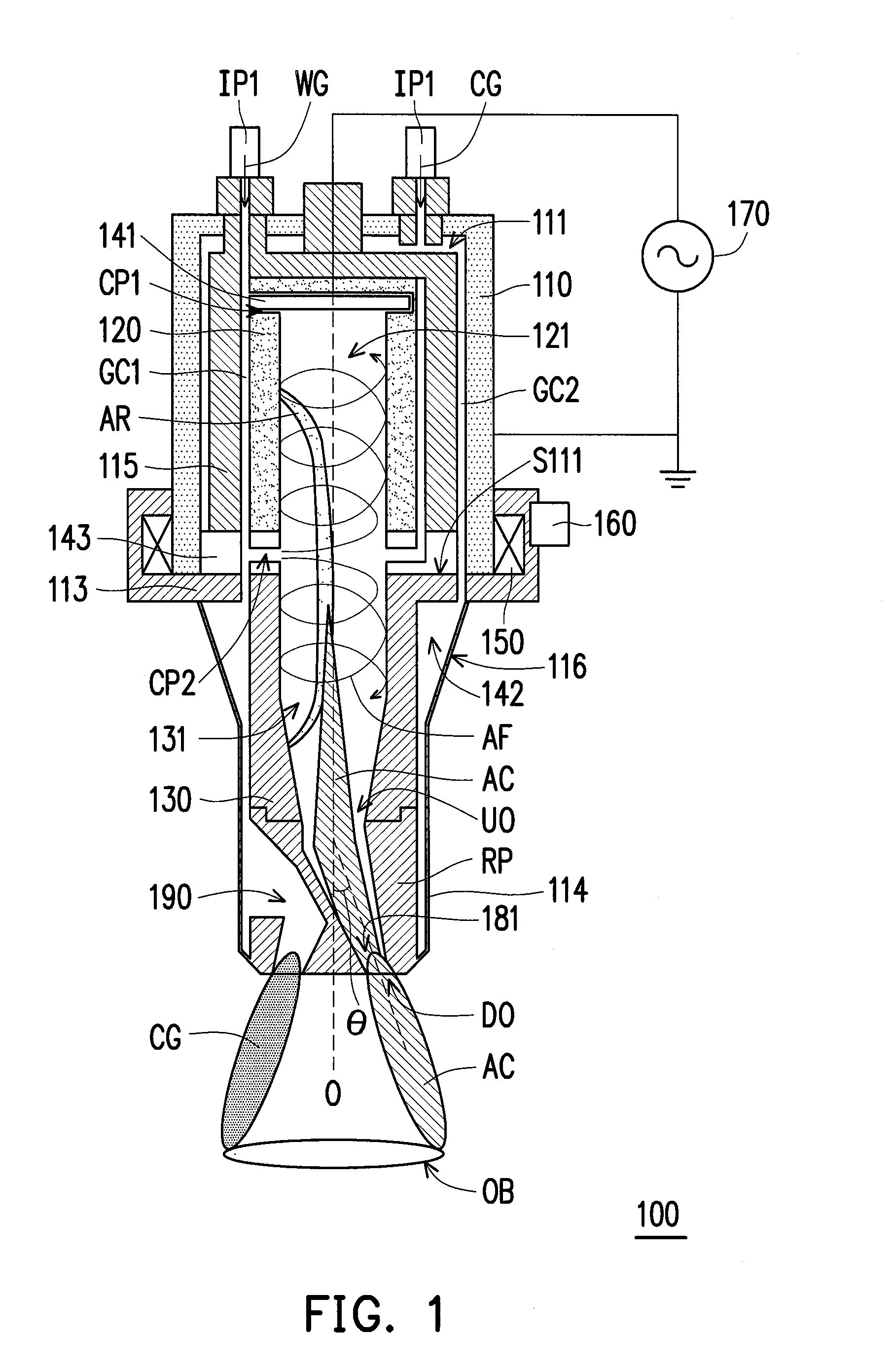
[0037]In view of the foregoing problems, the invention effectively solves these problems by disposing a gas ejection port nearby a plasma ejection outlet of a plasma device. Furthermore, implementations of a first electrode and a second electrode in the plasma device that are configured for generating the plasma are not limited to the shapes disclosed in the present embodiment, such that the first electrode and the second electrode may be tubular, rod-shaped or other shapes. Except that, when the first electrode and the second electrode are a tubular first tubular electrode and a tubular second tubular electrode, damages in the electrodes can effectively be avoided and reliability of the device may be enhanced. FIG. 1 is a schematic diagram illustrating architecture of a plasma device according to an embodiment of the invention. Referring to FIG. 1, in the present embodiment, a plasma device 100 includes a casing 110, a first tubular electrode 120, a second tubular electrode 130, a ...


PUM


Abstract

A plasma device including a casing, a first electrode, a second electrode, a nozzle and a gas ejection port is provided. The casing has a first chamber. The first electrode is disposed within the first chamber and has a second chamber. The second electrode capable of rotating in relative to the casing has a third chamber connected with the second chamber. The second chamber and the third chamber are adapted for accommodating plasma formed between the first electrode and the second electrode. The nozzle and the gas ejection port are independently disposed at the bottom of the second electrode respectively, wherein the nozzle is configured to eject the plasma, and forms an included angle with or is spaced a distance apart from a rotating axis of the second electrode. The gas ejection port is configured to eject cold gas.

Description

CROSS-REFERENCE TO RELATED APPLICATION[0001]This application claims the priority benefit of Taiwan application serial no. 103113891, filed on Apr. 16, 2014. The entirety of the above-mentioned patent application is hereby incorporated by reference herein and made a part of this specification.BACKGROUND OF THE INVENTION[0002]1. Field of the Invention[0003]The invention relates to a plasma device, and more particularly, to an atmospheric plasma device.[0004]2. Description of Related Art[0005]With the development of plasma technology, atmospheric arc plasma in the plasma has been widely applied to various fields of surface treatment. For example, the atmospheric arc plasma may be used to perform a surface treatment to an object to be treated, so as to enhance a reliability for performing a process, such as adhering, printing, packaging or epitaxizing, on a surface of this object. However, as being restricted by negative resistance characteristics of an electric arc, a process range of ...

Claims


Application Information

Patent Timeline
Patent Type & Authority Applications(United States)
IPC IPC(8): H01J37/32
CPCH01J37/32449H01J2237/006H01J37/32055H01J37/32596H05H1/34H05H1/3463H05H1/3468
Inventor HSU, YI-MINGWANG, LI-MINLI, AN-JEN
Owner CREATING NANO TECH INC
Why Eureka
Try Eureka