Fluid treatment system

a treatment system and flue gas technology, applied in water/sludge/sewage treatment, filtration separation, stationary filter element filters, etc., can solve the problems of insufficient room to utilize devices and inability to adapt to use, and achieve the effect of small footprin

Inactive Publication Date: 2006-07-18
TROJAN TECH
View PDF15 Cites 6 Cited by
  • Summary
  • Abstract
  • Description
  • Claims
  • Application Information

AI Technical Summary

Benefits of technology

[0015]Thus, the present inventors have developed a fluid treatment system which is capable of treating large volumes of fluid (e.g., water) while requiring a relatively small foot print. In essence, the present fluid treatment system concentrates a relatively large number of radiation sources in a relatively small amount of space resulting in the ability to treat large volumes of fluid (e.g., water).

Problems solved by technology

Unfortunately, the system described in the 896 patent is ideally suited for use in an open, channel-like system and is not readily adaptable to be used in a completely closed system where the flow of fluid is fed under pressure in a pipe.
Specifically, in many installations where it is desirable to treat large amounts of fluid (e.g., water), there is insufficient room to utilize a device such as that described in the 809, 980, 244 and 896 patents.

Method used


Image

  • Fluid treatment system
  • Fluid treatment system
  • Fluid treatment system

Examples


Embodiment Construction

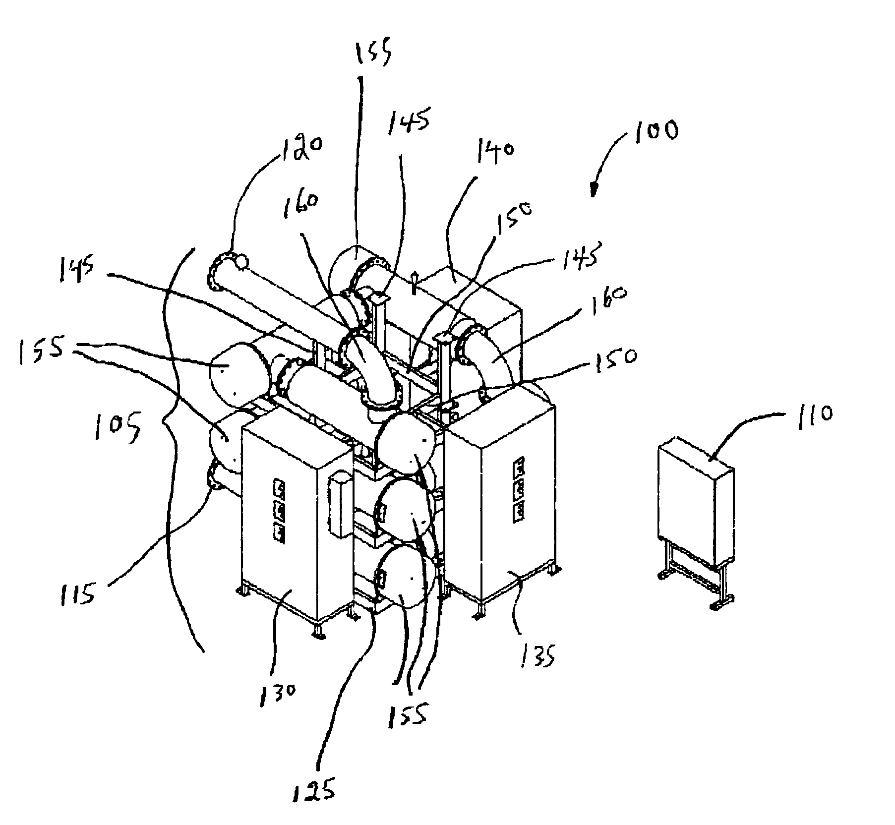
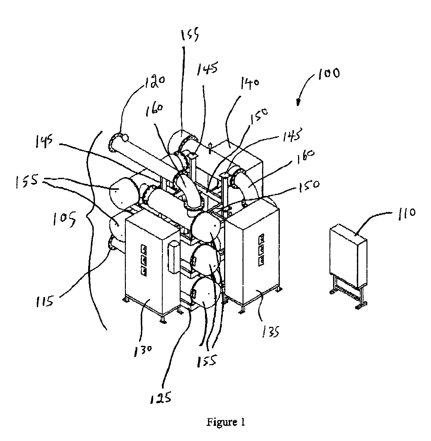
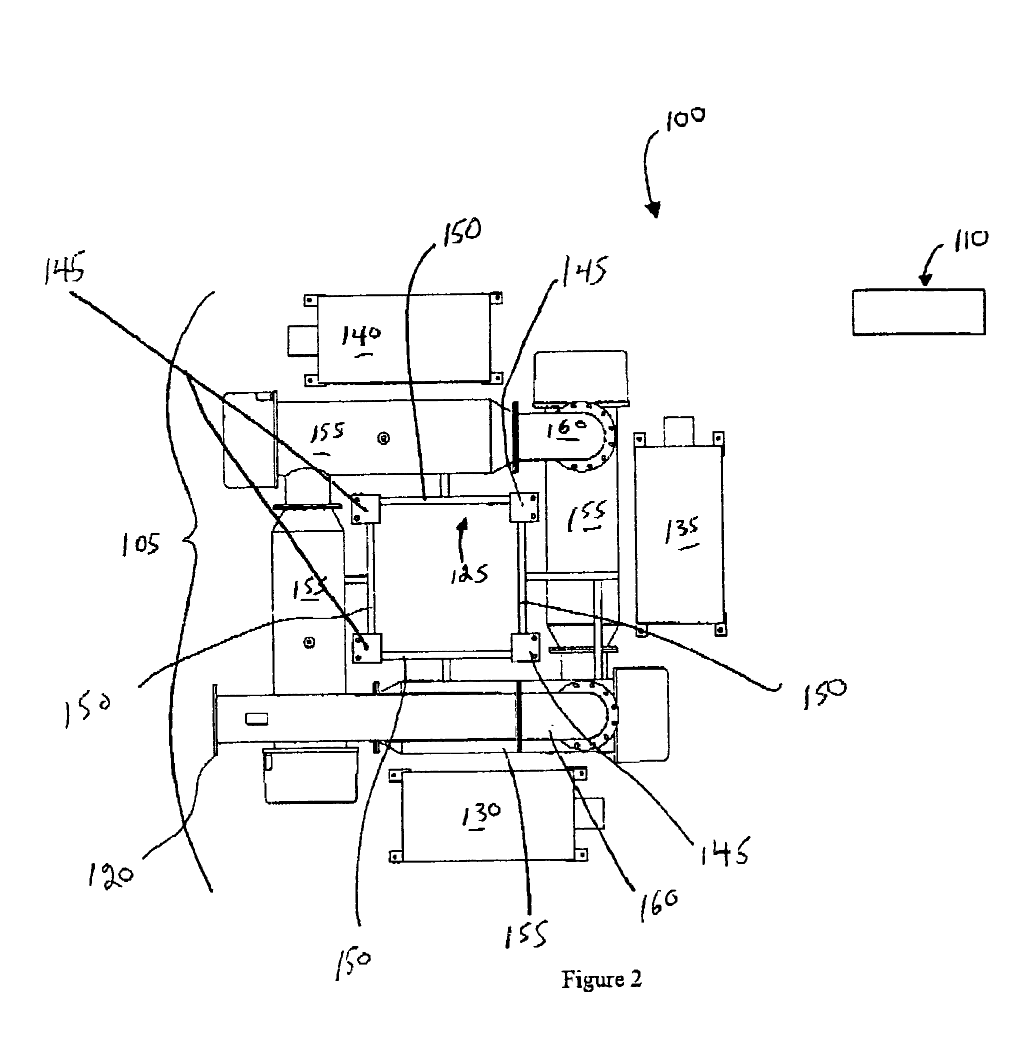
[0024]Thus, with reference to FIGS. 1–4, there is illustrated a fluid treatment system 100. Fluid treatment system 100 comprises a fluid treatment system reactor array 105 and a master control panel 110 which is remote from fluid treatment reactor array 105.

[0025]Fluid treatment reactor array 105 comprises an inlet 115 and an outlet 120. Fluid treatment reactor array 105 further comprises a skid 125. Fluid treatment reactor array 105 further comprises a trio of power control panels 130,135,140.

[0026]Skid 125 comprises a grid-like series of vertical supports 145 which are interconnected to a series of horizontal supports 150.

[0027]The network of vertical supports 145 and horizontal supports 150 provides a support system for nine radiation reactors 155. The design of each reactor 155 is the same and will be described in more detail below.

[0028]As shown in FIGS. 1–4, the radiation reactors are stacked in rows of three on top of one another. This arrangement is facilitated through the u...


PUM

PropertyMeasurementUnit
diametersaaaaaaaaaa
diametersaaaaaaaaaa
diametersaaaaaaaaaa

Abstract

There is described a fluid treatment system comprising an array of independent fluid treatment reactors. The reactors are arranged in a manner whereby a flow of fluid may be passed through the array in a substantially helical direction. The fluid treatment system is capable of treating large volumes of fluid (e.g., water) while requiring a relatively small foot print. In essence, the present fluid treatment system concentrates a relatively large number of radiation sources in a relatively small amount of space resulting in the ability to treat large volumes of fluid (e.g., water).

Description

CROSS-REFERENCE TO RELATED APPLICATION[0001]The present application claims the benefit under 35 U.S.C. §119(e) of provisional patent application Ser. No. 60 / 323,383, filed Sep. 20, 2001, the contents of which are hereby incorporated by reference.BACKGROUND OF THE INVENTION[0002]1. Field of the Invention[0003]In one of its aspects, the present invention relates to a fluid treatment system. In another of its aspects, the present invention relates to a method of treating fluid.[0004]2. Description of the Prior Art[0005]Fluid treatment devices and systems are known. For example, U.S. Pat. Nos. 4,482,809, 4,872,980, 5,006,244 and U.S. Re. Pat. No. 36,896 (all assigned to the assignee of the present invention) all describe gravity fed fluid treatment systems which employ ultraviolet (UV) radiation to inactivate microorganisms present in the fluid.[0006]The devices and systems described in the 809, 980 and 244 patents generally include several UV lamps each of which are mounted within slee...

Claims


Application Information

Patent Timeline
Patent Type & Authority Patents(United States)
IPC IPC(8): C02F1/32A61L2/08B01D53/75B01J19/12B01J19/24
CPCA61L2/08A61L2/10B01D53/75B01J19/123B01J19/243C02F1/325B01J2219/00038C02F2301/026B01J2219/0877C02F2201/3227C02F2201/324C02F2301/022B01J2219/0004C02F1/32
Inventor WILLIAMSON, CHRISTIANPENHALE, DOUGLASROGER, SCOTT
Owner TROJAN TECH
Why Eureka
Try Eureka