Heat sink having two or more separated channels arranged vertically with common inlet and common outlet

Active Publication Date: 2015-10-22
LG ENERGY SOLUTION LTD
View PDF8 Cites 7 Cited by
  • Summary
  • Abstract
  • Description
  • Claims
  • Application Information

AI Technical Summary

Benefits of technology

[0018]Two or more separated cooling channels according to the present disclosure have a shorter movement distance than a related art. Thus, as compared to the related art, a rate at which the temperature rises with the increasing distance from an inlet of the cooling channel is relatively low. That is, the problem of the related art, i.e., the cooling efficien

Problems solved by technology

The above problem of the related art causes a temperature gradient of the secondary battery, and the t

Method used


Image

  • Heat sink having two or more separated channels arranged vertically with common inlet and common outlet
  • Heat sink having two or more separated channels arranged vertically with common inlet and common outlet
  • Heat sink having two or more separated channels arranged vertically with common inlet and common outlet

Examples


Example

[0028]Hereinafter, preferred embodiments of the present disclosure will be described in detail with reference to the accompanying drawings. Prior to the description, it should be understood that the terms used in the specification and the appended claims should not be construed as limited to general and dictionary meanings, but interpreted based on the meanings and concepts corresponding to technical aspects of the present disclosure on the basis of the principle that the inventor is allowed to define terms appropriately for the best explanation. Therefore, the description proposed herein is just a preferable example for the purpose of illustrations only, not intended to limit the scope of the disclosure, so it should be understood that other equivalents and modifications could be made thereto without departing from the spirit and scope of the disclosure.

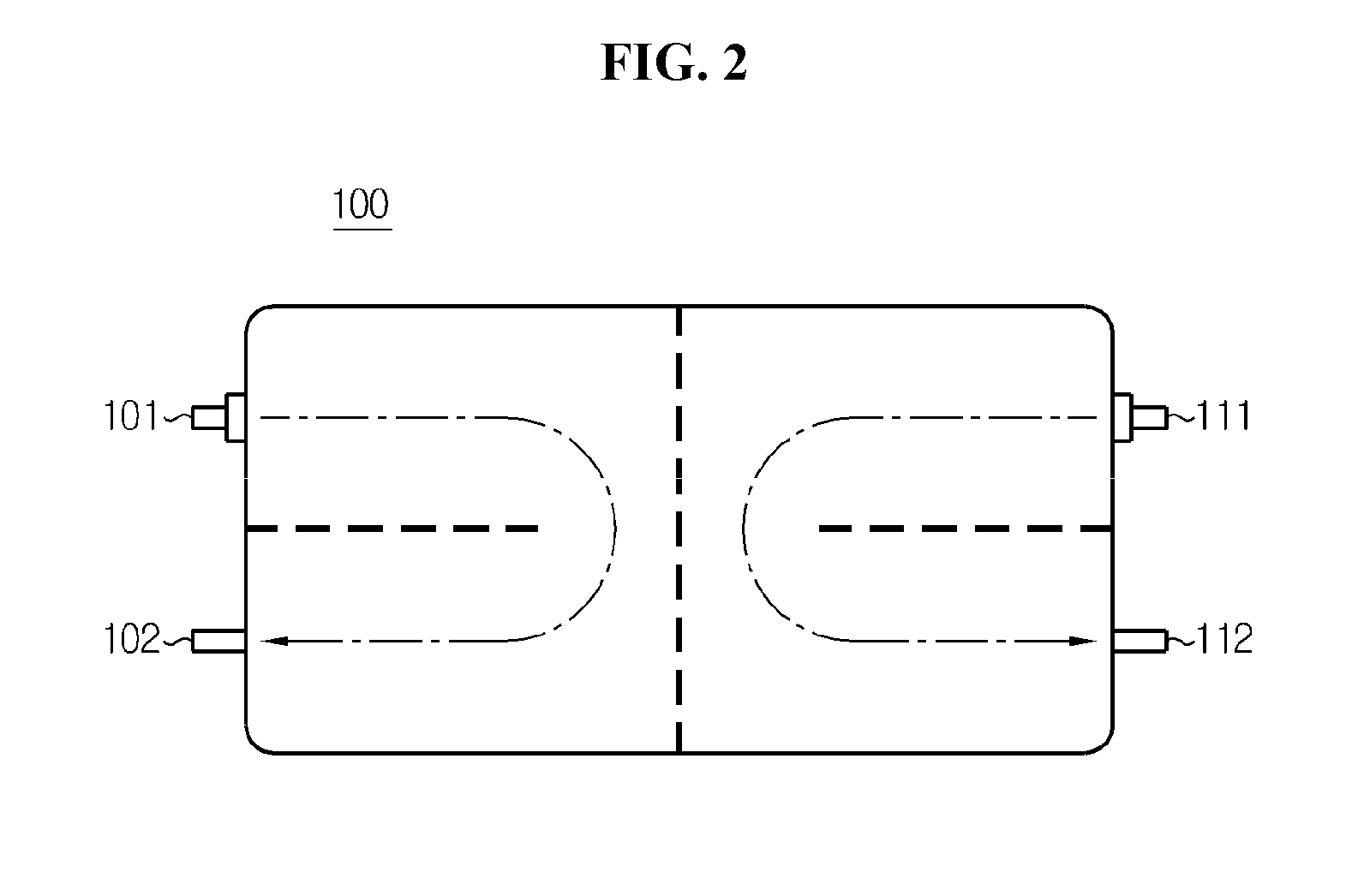
[0029]FIGS. 2 and 3 are cross-sectional views illustrating heat sinks 100 and 200 with two or more separated cooling channels.

[003...


PUM


Abstract

The present disclosure discloses a heat sink with two or more separated channels. The heat sink according to the present disclosure includes a cooling channel through which a refrigerant passes to cool a secondary battery by an indirect cooling method, the secondary battery including a cell assembly in which at least two unit cells are stacked, each unit cell including a positive electrode plate, a separator, and a negative electrode plate, and a plurality of positive and negative electrode tabs protruding from the positive and negative electrode plates of each unit cell is electrically connected to positive and negative leads, respectively, wherein the cooling channel has two or more separated channels, the two or more separated channels have branches inside to allow a coolant to flow in each of the channels, and the branches are vertically arranged. According to the present disclosure, provision of a heat sink having a uniform cooling effect is enabled.

Description

TECHNICAL FIELD[0001]The present disclosure relates to a heat sink, and more particularly, to a heat sink having two or more separated channels arranged vertically with a common inlet and a common outlet.[0002]The present application claims priority to Korean Patent Application No. 10-2013-0124716 filed in the Republic of Korea on Oct. 18, 2013 and Korean Patent Application No. 10-2014-0140059 filed in the Republic of Korea on Oct. 16, 2014, the disclosures of which are incorporated herein by reference.BACKGROUND ART[0003]Due to its characteristics of being easily applicable to various products and electrical properties such as a high energy density, a secondary battery is not only commonly applied to a portable device, but universally applied to an electric vehicle (EV) or a hybrid electric vehicle (HEV) and an energy storage system that is propelled by an electric motor. This secondary battery is gaining attention for its primary advantage of remarkably reducing the use of fossil ...

Claims


Application Information

Patent Timeline
IPC IPC(8): H01M10/6556H01M2/10H01M50/204
CPCH01M2/1016H01M10/6556H01M10/647H01M10/617H01M10/6566H01M10/613F28F3/12F28D2021/0029Y02E60/10H01M50/204H01M10/60H01M10/65H01M10/6554H01M10/6555H01M10/6568H01M10/6551H01M50/258H01M10/441H01M2010/4271H01M2220/20H01M2220/30
Inventor JUNG, SEUNG-HUNKIM, MIN-JUNGKANG, DAL-MO
Owner LG ENERGY SOLUTION LTD
Why Eureka
Try Eureka