Nut disassembling device

a disassembly device and nut technology, which is applied in the field of disassembly devices, can solve the problems of affecting nut wear, and needing to be improved, so as to improve the abrasion resistance of parts, improve the performance of clamping, and facilitate the disassembly of nuts.

Inactive Publication Date: 2015-10-29
CHEN JUN FAN
View PDF6 Cites 1 Cited by
  • Summary
  • Abstract
  • Description
  • Claims
  • Application Information

AI Technical Summary

Benefits of technology

[0008]The support rod includes a third threaded portion and two tightening members screwed to the third threaded portion. The center pillar includes a first through hole and a second through hole, the first through hole is for penetration of the adjustment member, and the second through hole is for penetration of the third threaded portion of the support rod. Each clamping block includes a clamping portion, a third through hole and a fourth through hole, and the fourth through hole locates between the clamping portion and the third through hole. The adjustment member inserts in the third through hole or the fourth through hole and is able to drive the clamping block to move. The other of the third and fourth through holes which unpenetrates through the adjustment member is movably disposing around the third threaded portion of the support rod. The tightening members are disposed on the support rod, and when each of the tightening members rotates relative to the support rod, the clamping block is moved by the tightening member.
[0009]When clamping a nut and disassembling it, the tightening member is rotatable to drive the clamping portion to farther abut against the nut tightly. It improves the performance of clamping the nut, so that it is convenient for disassembling the nut. It also improves the abrasion of a part and elongates a usage life of a structure.

Problems solved by technology

In prior arts, a reaction force occurs when a nut disassembling structure abuts against a nut, and it makes the clamping performance bad.
So that the nut wears down while applying forces on it in a disassembling process, and this disadvantage is needed to be improved.

Method used


Image

  • Nut disassembling device
  • Nut disassembling device
  • Nut disassembling device

Examples


Embodiment Construction

[0014]The present invention will be clearer from the following description when viewed together with the accompanying drawings, which show, for purpose of illustrations only, the preferred embodiment in accordance with the present invention.

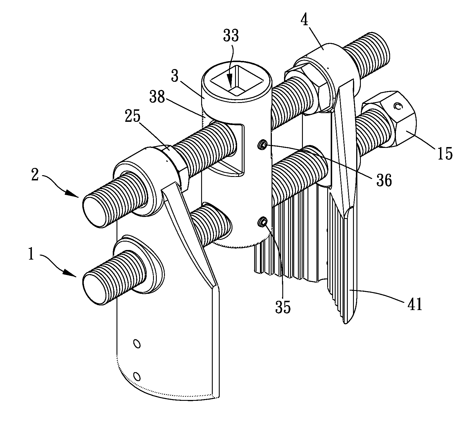
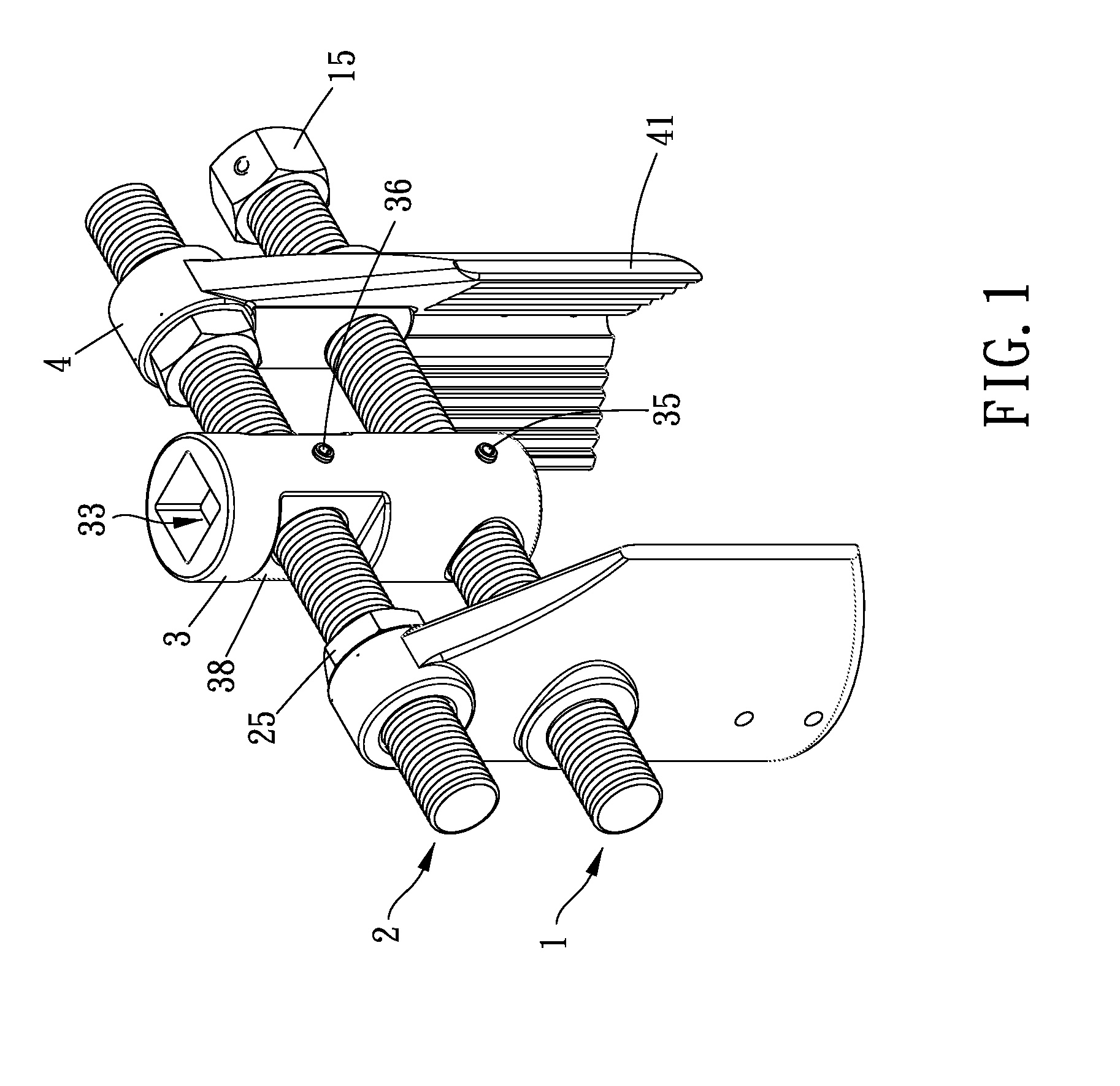
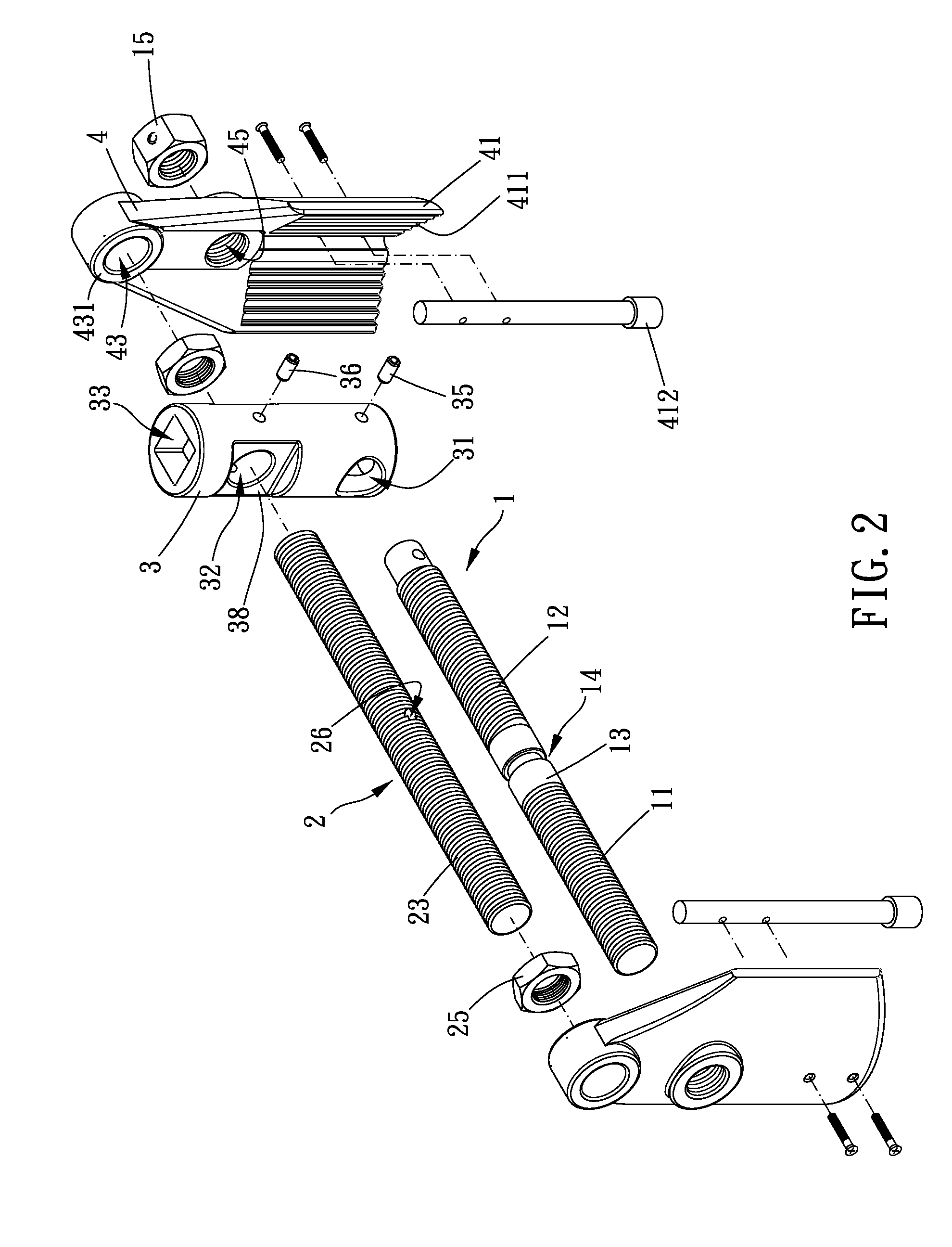
[0015]Referring to FIGS. 1-3, a nut disassembling device includes an adjustment member 1, a support rod 2, a center pillar 3 and two clamping blocks 4.

[0016]The adjustment member 1 includes a first threaded portion 11, a second threaded portion 12 and a middle portion 13. The thread direction of the first threaded portion 11 is opposite to that of the second threaded portion 12. The middle portion 13 locates between the first threaded portion 11 and the second threaded portion 12. The middle portion 13 is formed with a circular slot 14. Besides, the adjustment member 1 is formed with a driving part 15 at one end, and the driving part 15 includes a polygonal outer circumferential surface. The driving part 15 is for connecting with a tool (such as ...


PUM


Abstract

A nut disassembling device is provided, comprising an adjustment member, a support rod, a center pillar and two clamping blocks. The support rod is screwed with two tightening members. Each of the tightening members is rotatable relative to the support rod, and the clamping block is moved by the tightening member. Thus, during the clamping of the nut, the clamping blocks close and push the nut through rotation of the tightening members, and it effectively improves the clamping for installation and uninstallation of the nut.

Description

BACKGROUND OF THE INVENTION[0001]1. Field of the Invention[0002]The present invention relates to a nut disassembling device, and more particularly to a disassembling structure for nuts on vehicle tires.[0003]2. Description of the Prior Art[0004]In prior arts, a reaction force occurs when a nut disassembling structure abuts against a nut, and it makes the clamping performance bad. So that the nut wears down while applying forces on it in a disassembling process, and this disadvantage is needed to be improved.[0005]The present invention has arisen to mitigate and / or obviate the afore-described disadvantages.SUMMARY OF THE INVENTION[0006]The primary object of the present invention is to provide a nut disassembling device to improve the performance of clamping a nut.[0007]To achieve the above object, a nut disassembling device in accordance with present invention comprises an adjustment member, a support rod, a center pillar and two clamping blocks.[0008]The support rod includes a third...

Claims


Application Information

Patent Timeline
Patent Type & Authority Applications(United States)
IPC IPC(8): A47J43/26
CPCA47J43/26
Inventor CHEN, JUN-FAN
Owner CHEN JUN FAN
Why Eureka
Try Eureka