

Coupling device of jig
- Summary
- Abstract
- Description
- Claims
- Application Information
AI Technical Summary
Benefits of technology
Problems solved by technology
Method used
Image

Examples
Embodiment Construction
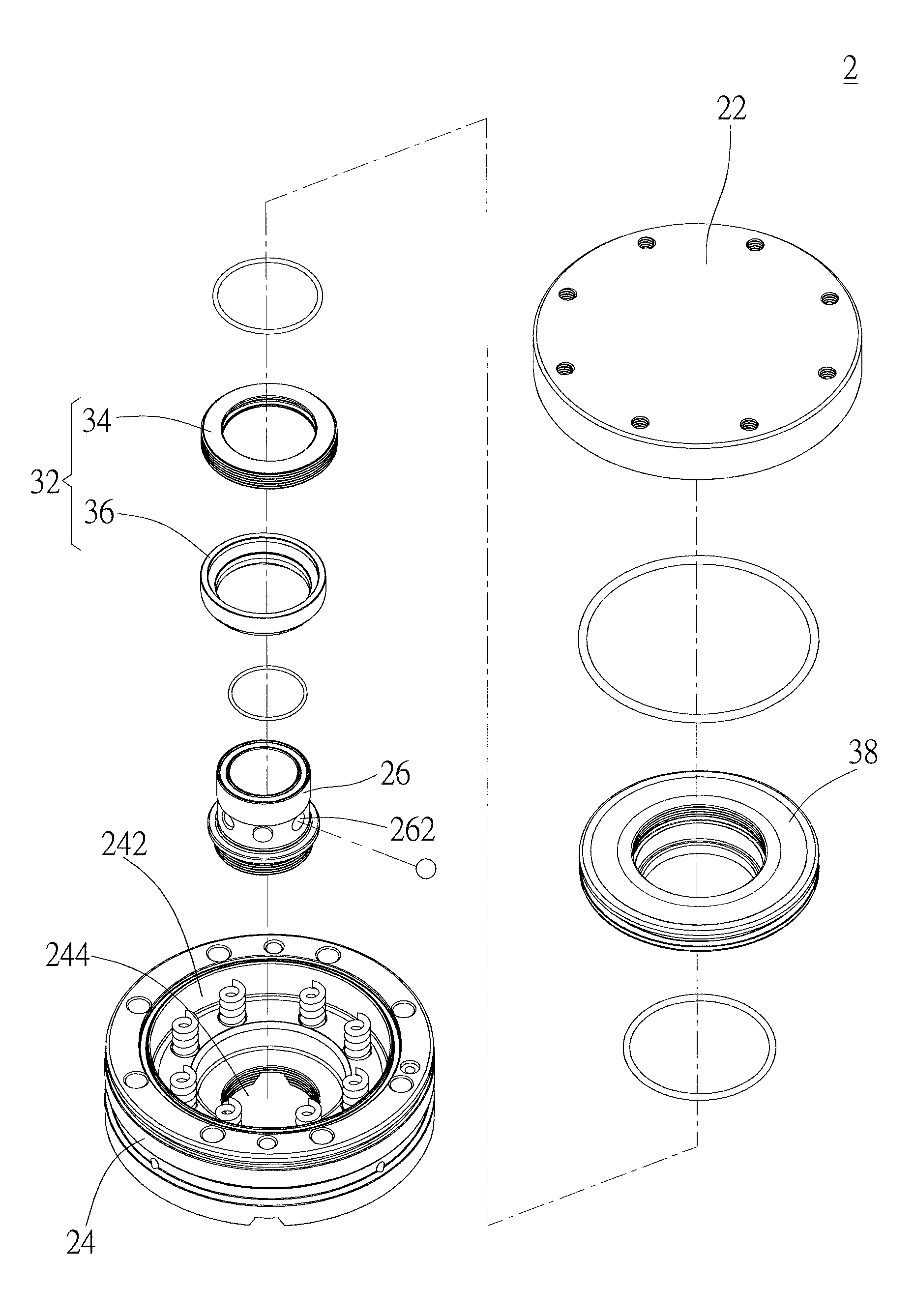
[0023]As shown in FIG. 3 to FIG. 7, a coupling device 2 of the first preferred embodiment of the present invention includes a foundation 20, a tube 26, a plurality of balls 28, and a piston base 30. The coupling device 2 is coupled to a jig 3, which includes a plug 46, and the plug 46 has a head 462 and a neck 464.
[0024]The foundation 20 has a top seat 22 and a bottom seat 24 connected to the top seat 22, wherein the top seat 22 is used for placing workpieces (not shown), and the bottom seat 24 touches a surface of the jig 3. The bottom seat 24 has a chamber 242 and a perforation 244 which connects the chamber 242 to an exterior of the foundation 20.
[0025]An end of the tube 26 is inserted into the perforation 244 of the bottom seat 24 to enter the chamber 242. More specifically, a part of the tube 26 is inside the chamber 242, and the rest is inside the perforation 244. The tube 26 has an outer screw thread adjacent to a distal end thereof, and the perforation 244 has a correspondin...
PUM
 Abstract
Description
Claims
Application Information