Deburring Brush

Active Publication Date: 2015-10-29
KSM CASTINGS QINHUANGDAO
View PDF6 Cites 5 Cited by
  • Summary
  • Abstract
  • Description
  • Claims
  • Application Information

AI Technical Summary

Problems solved by technology

During manufacturing process of aluminum alloy wheels, deburring cost accounts for a very large part of the overall cost due to huge consumption of deburr

Method used


Image

  • Deburring Brush
  • Deburring Brush

Examples


Embodiment Construction

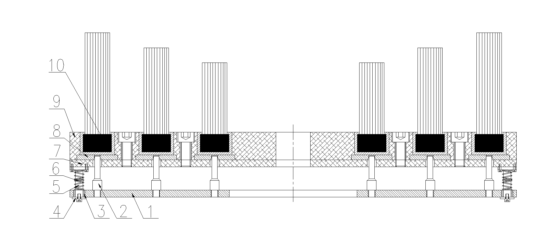
[0012]Details and operation of the specific device provided by the present invention will be described below in conjunction with the accompanying drawings.

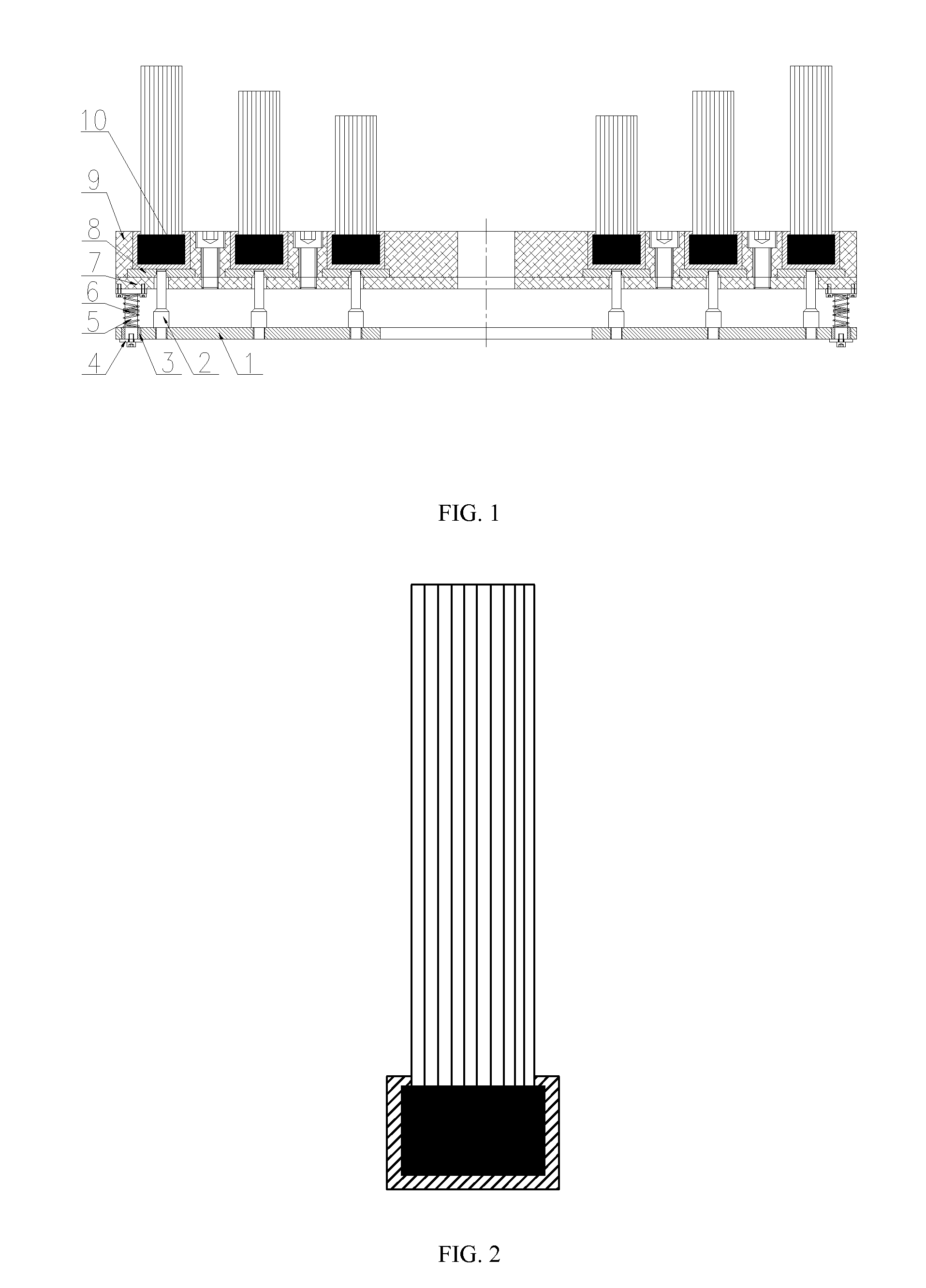
[0013]The deburring brush comprises a pressing plate 1, jacking posts 2, copper sleeves 3, gaskets 4, guide posts 5, springs 6, a bottom plate 7, magnets 8, a top plate 9 and bristle units 10. The magnets 8 are fixed between the bottom plate 7 and the top plate 9, and the magnets 8 grip the bristle units 10, thus forming a body of the deburring brush.

[0014]The guide posts 5 are fixed below the bottom plate 7, and the copper sleeves 3 cooperating with the guide posts 5 are embedded on the pressing plate 1; the pressing plate 1, above which are mounted the jacking posts 2, is fixed between the springs 6 and the gaskets 4 at the ends of the guide posts 5; and the top ends of the jacking posts 2 pass through holes of the bottom plate 7 and the magnets 8, and are in contact with the bottoms of the bristle units 10.

[0015]During operatio...


PUM


Abstract

The present invention discloses a deburring brush, comprising a pressing plate, jacking posts, copper sleeves, gaskets, guide posts, springs and bristle units. When the bristle units need replacement, it only needs to place the deburring brush on the ground and then press down edges of the front side of a top plate, so that all the bristle units will fall off against the suction force of strong magnets under the action of each jacking post. According to the present invention, it avoids being time consuming and labor intensive due to removing the bristle units one by one by using a screw driver or other similar devices while replacing the bristle units, and at the same time the replacing speed of bristles is greatly increased.

Description

TECHNICAL FIELD[0001]The present invention relates to a surface treatment device, more particularly to a metal surface treatment device.BACKGROUND ART[0002]During manufacturing process of aluminum alloy wheels, deburring cost accounts for a very large part of the overall cost due to huge consumption of deburring brushes. More and more enterprises have begun exploring and developing a variety of novel deburring brushes to reduce the deburring cost. A deburring brush with replaceable bristles is a future development trend of wheel deburring brushes due to its flexibility, its chassis part being reusable, thus greatly reducing the cost. However, how to make it convenient to disassemble the shortened bristles while reducing the cost is a new technical problem we are faced with.[0003]Invention Contents:[0004]An object of the present invention is providing a wheel deburring brush with conveniently replaceable bristles.[0005]To achieve the above object, the present invention adopts the fol...

Claims


Application Information

Patent Timeline
IPC IPC(8): B24D13/10A46B5/00B24B9/04
CPCB24D13/10A46B5/0095B24B9/04A46B7/04A46B9/026A46B2200/3086A46B2200/3093
Inventor XUE, BOWENGUO, JIANDONGWANG, YONGNINGZHU, ZHIHUALI, CHANGHAI
Owner KSM CASTINGS QINHUANGDAO
Why Eureka
Try Eureka