
Crimping machine control system and crimping machine

A technology of control system and crimping machine, which is applied in the field of crimping machines, can solve the problems of low efficiency and low replacement speed, and achieve the effect of reducing loss and improving replacement speed and efficiency

Active Publication Date: 2019-12-13
河北沃福科技有限公司
View PDF11 Cites 2 Cited by
  • Summary
  • Abstract
  • Description
  • Claims
  • Application Information

AI Technical Summary

Problems solved by technology

[0004] In order to solve the problems of low replacement speed and low efficiency in the prior art, the present invention provides a crimping machine control system and a crimping machine, which have the characteristics of faster replacement speed and higher efficiency

Method used


Image

  • Crimping machine control system and crimping machine
  • Crimping machine control system and crimping machine
  • Crimping machine control system and crimping machine

Examples


Embodiment Construction

[0029] In order to make the purpose, technical solution and advantages of the present invention clearer, the technical solution of the present invention will be described in detail below. Apparently, the described embodiments are only some of the embodiments of the present invention, but not all of them. Based on the embodiments of the present invention, all other implementations obtained by persons of ordinary skill in the art without making creative efforts fall within the protection scope of the present invention.

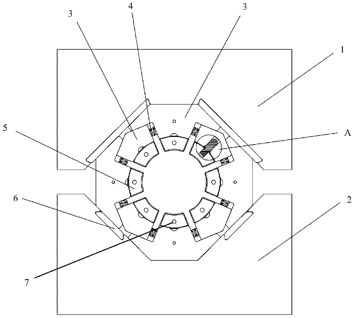
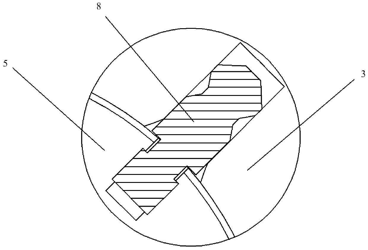
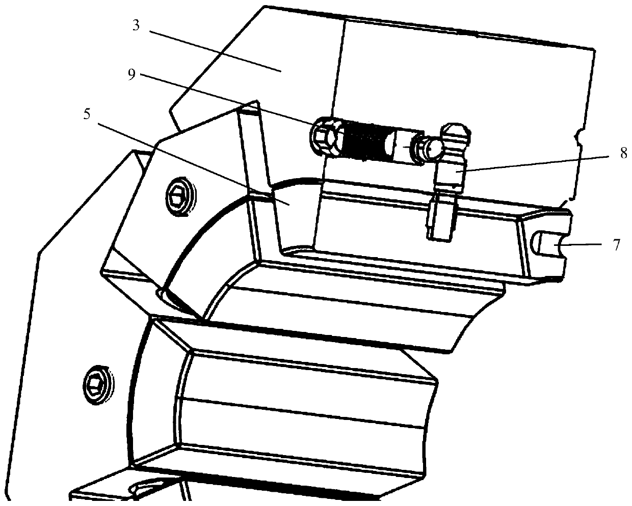
[0030] refer to Figure 1 to Figure 4 as well as Image 6 As shown, the embodiment of the present invention provides a crimping machine control system, including: a position sensor and a control platform;

[0031] The position sensor is used to obtain the position information of the slider in real time, and send the obtained position information to the control platform in real time;

[0032] After the control platform obtains the first mold change command, th...


PUM


Abstract

The invention relates to a crimping machine control system. The crimping machine control system comprises a position sensor and a control platform, wherein the position sensor is used for acquiring the position information of a sliding block in real time and transmitting the acquired position information to the control platform in real time; the control platform controls the sliding block to moveto a first preset position to make a plug on a quick-change handle to be in one-to-one correspondence with the jack position on a die head after obtaining a first die-change instruction; and the control platform controls the sliding block to move to a second preset position to separate an annular pin on the die head from a die seat to take out the die head after acquiring a second die change instruction. The invention has the beneficial effects that in the process of replacing the die head, a user only needs to input the corresponding control instructions on the control platform and perform the corresponding operations after the sliding block moves in place, and repeated contraction and expansion debugging are not needed, so that the replacement speed and efficiency of a die are improved,and meanwhile, the loss of a crimping driving mechanism is reduced.

Description

technical field [0001] The invention belongs to the technical field of crimping machines, and in particular relates to a crimping machine control system and a crimping machine. Background technique [0002] The crimping machine is a machine for crimping pipe fittings. Its principle is to apply shrinkage force to the metal joint through the crimping die of the crimping machine, and crimp the metal joint on the matching rubber pipe fitting. Usually, the upper and lower seats are used to enclose the accommodation space of the mold seat, and one seat is fixed and the other is movable. Generally, 6 to 8 mold seats are used, and the mold head is installed on the inner surface of the mold seat to form a metal In the space of the joint, a return spring is provided between two adjacent mold seats, and the cylinder piston pushes the slider (upper seat or lower seat) to move so that the mold seat drives the die head to shrink and squeeze the metal joint. In the crimping mold of the co...

Claims


Application Information

Patent Timeline
Patent Type & Authority Applications(China)
IPC IPC(8): B29C65/58B29C65/64B29C33/30
CPCB29C33/306B29C65/58B29C65/64B29C66/534B29C66/742
Inventor 吴巧武献昌
Owner 河北沃福科技有限公司
Learn More