Light-transmitting imprinting mold and method for manufacturing large-area mold

a technology of imprinting molds and imprinting patterns, which is applied in the direction of manufacturing tools, photomechanical equipment, instruments, etc., can solve the problems of difficult enlargement of molds with nano-scale fine concave-convex patterns on their surface, high cost, etc., and achieves modest accuracy, easy deformation, and easy deformation

Inactive Publication Date: 2015-10-29
SOKEN CHEM & ENG CO LTD
View PDF4 Cites 10 Cited by
  • Summary
  • Abstract
  • Description
  • Claims
  • Application Information

AI Technical Summary

Benefits of technology

[0012]In Patent Literature 1, a light shielding member is provided at a non-patterned portion. Here, the present invention has a different basic concept, and a light shielding member need be provided so as to cover the concave-convex pattern of the mold and so that the surface profile of the light shielding member reproduce the concave-convex pattern. When such light shielding member is provided, difference in degree of exposure regarding the photo curing resin can be provided between the region having the light shielding member (light shielding region) and the other region (light transmitting region). Then, by adjusting the amount of exposure, the liquid-state photo curing resin in the light shielding region can be semi-cured to a degree in which the profile of the reverse pattern of the concave-convex pattern is maintained for a short period of time.
[0013]Subsequently, the mold is arranged so that the light transmitting region of the mold is positioned on the semi-cured photo curing resin. When the concave-convex pattern of the mold is pressed, the pattern already formed on the semi-cured photo curing resin easily deforms so as to have a reverse pattern profile following the concave-convex pattern of the mold newly pressed. Since the semi-cured photo curing resin can be easily deformed, the pattern already formed would not be destroyed, but is deformed into a new reverse pattern.
[0014]When the mold of the present invention is used, the alignment of the mold is considered sufficient with a level at which the mold is moved so that the edge of the light transmitting region is positioned on the semi-cured photo curing resin. Therefore, alignment need not be done with high accuracy as in Patent Literature 1, allowing forming of continuous reverse pattern of the concave-convex pattern of the mold even by use of a relatively reasonably priced imprint apparatus with modest accuracy.

Problems solved by technology

Here, molds having a nano-scale fine concave-convex pattern on its surface are expensive since it takes long time to form the pattern.
Therefore, it is difficult to enlarge molds having the nano-scale fine concave-convex pattern on its surface (large-area molds).

Method used


Image

  • Light-transmitting imprinting mold and method for manufacturing large-area mold
  • Light-transmitting imprinting mold and method for manufacturing large-area mold
  • Light-transmitting imprinting mold and method for manufacturing large-area mold

Examples


first embodiment

1. First Embodiment

1-1. Light-Transmitting Imprint Mold

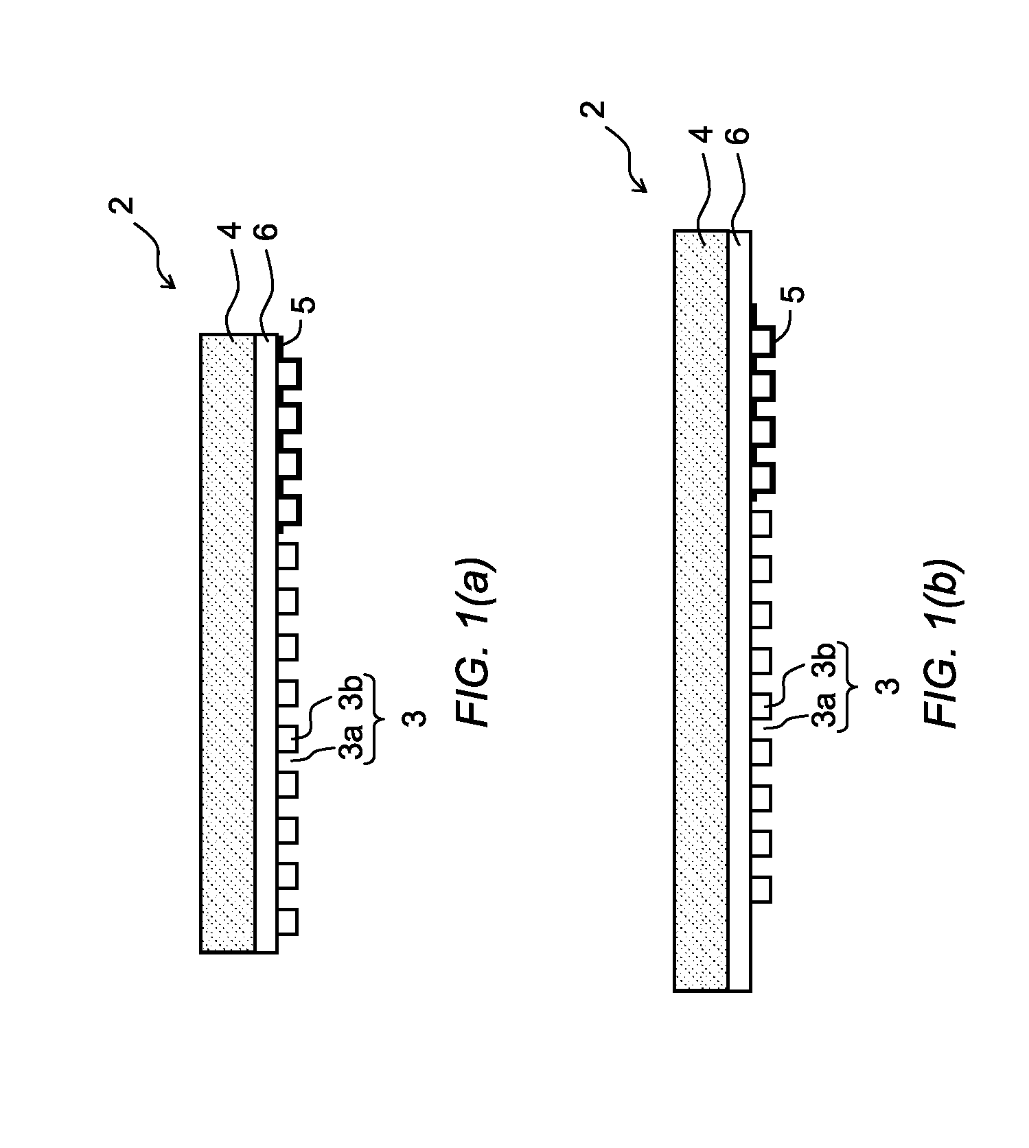
[0031]As shown in FIG. 1(a), the light-transmitting imprint mold of the first embodiment of the present invention is a light-transmitting imprint mold 2 comprising a transparent substrate 4 having a patterned region onto which a concave-convex pattern 3 is formed, and a light shielding member 5 provided on the patterned region. Here, the light shielding member 5 is provided at the edge portion of the patterned region so as to cover the concave-convex pattern 3, both of the concave portion 3a and the convex portion 3b being continuously covered. In addition, the surface profile of the light shielding member reproduces the concave-convex pattern 3.

[0032]Such imprint mold 2 can be formed using a known imprint technique. In one example, as shown in FIG. 1(a), the imprint mold comprises a transparent substrate 4, and a transparent resin layer 6 provided on the transparent substrate 4, the transparent resin layer 6 having a desired fi...

second embodiment

2. Second Embodiment

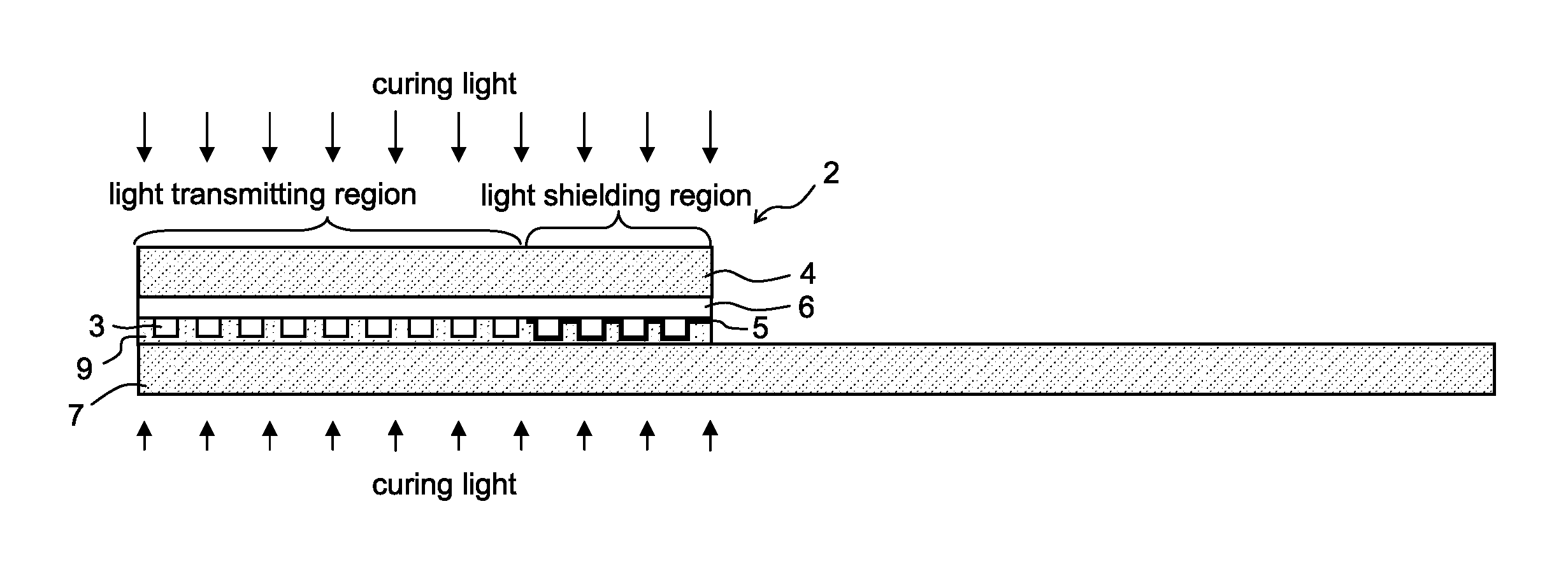
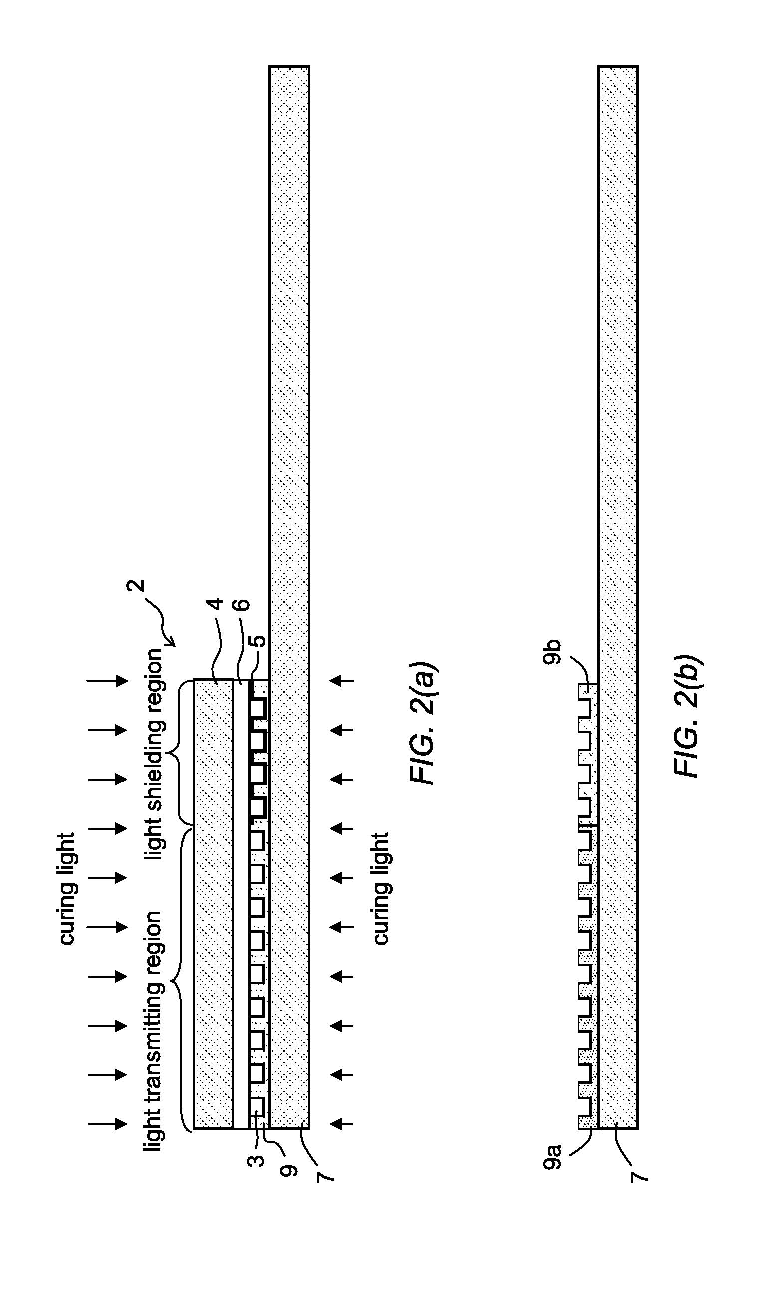
[0059]FIG. 4 shows the light-transmitting imprint mold 2 according to the second embodiment of the present invention. The constitution of the mold 2 is similar to that of the first embodiment, however, the light shielding member 5 attenuates the curing light.

[0060]When such mold is used, as shown in FIG. 5, the photo curing resin 9 is irradiated with the curing light from only the mold 2 side. In the light transmitting region, the curing light transmits the mold 2 as it is. Accordingly, the photo curing resin 9 is irradiated with the curing light. In the light shielding region, the curing light is attenuated by the light shielding member 5. Accordingly, the photo curing resin 9 is irradiated with attenuated curing light. By adjusting the strength of the curing light and the transmittancy of the light shielding member 5, the photo curing resin 9 can be semi-cured. The succeeding step can be conducted in a similar manner as the first embodiment.


PUM

PropertyMeasurementUnit
thicknessaaaaaaaaaa
thicknessaaaaaaaaaa
pressing pressureaaaaaaaaaa

Abstract

An imprint method including the steps of: an exposing step to irradiate a photo curing resin, coated on a large-area substrate, with a curing light while the light-transmitting imprint mold is pressed against the photo curing resin, an amount of the curing light applied onto the photo curing resin in a light shielding region provided with the light shielding member made less than an amount of the curing light applied onto the photo curing resin in a light transmitting region of the mold so that a portion of the photo curing resin in the light shielding region is semi-cured by the use of the light shielding member provided so as to reproduce the concave-convex pattern of the transparent substrate.

Description

TECHNICAL FIELD[0001]The present invention relates to a light-transmitting imprint mold, and to a method for manufacturing a large-area mold.BACKGROUND[0002]Imprint technology is a fine processing technology, which uses a mold having a reverse pattern of the desired fine concave-convex pattern. The mold is pressed against a transferring material on a substrate, thereby transferring the pattern of the mold onto the transferring material. Here, the transferring material is a liquid-state resin for example. The fine concave-convex pattern can vary between a nano-scale pattern of 10 nm-level size to a 100 μm-level size. The reverse pattern is used in a wide range of field including semiconductor materials, optical materials, recording media, micro machines, biotechnology, and environmental protection.[0003]Here, molds having a nano-scale fine concave-convex pattern on its surface are expensive since it takes long time to form the pattern. Therefore, it is difficult to enlarge molds havi...

Claims


Application Information

Patent Timeline
Patent Type & Authority Applications(United States)
IPC IPC(8): B29C35/08B29C59/02
CPCB29C35/0888B29K2995/0026B29C35/0805B29C59/02B29C35/0894B29C59/022B29C59/026G03F7/0002B29C2059/023B29C2035/0827
Inventor MIYAZAWA, YUKIHIRO
Owner SOKEN CHEM & ENG CO LTD
Why Eureka
Try Eureka