Robot for transporting storage bins

a robot and storage bin technology, applied in the field of remote operation vehicles, can solve the problems of undesired speed reduction, limit the maximum handling weight of the robot, etc., and achieve the effects of effective removal of undesired torque, high degree of symmetry, and improved stability of the robot or vehicl

Active Publication Date: 2015-10-29
AUTOSTORE TECH AS
View PDF16 Cites 51 Cited by
  • Summary
  • Abstract
  • Description
  • Claims
  • Application Information

AI Technical Summary

Benefits of technology

[0017]The central arrangement of the cavity in the vehicle body relative to the second direction (Y) effectively remove the undesired torque, thereby improving the stability of the robot or vehicle. This arrangement also results in a lifting and transporting process having a weight distribution with a high degree of symmetry. Furthermore, the novel design allows the same vehicle to be used for lifting and transporting storage bins of heights significantly less than the cavity height (i.e. the height extending from the suspension points of the lifting device and to the lower edge of the vehicle) since the framework/body surrounding at least part of the bin receiving cavity effectively hinders any undesired bin reeling/wobbling. The presence of the cavity surrounding body also allows maintaining full or nearly full lifting speed almost all the way to its end position within the cavity, as well as initiation of stable bin transportations towards the deliv...

Problems solved by technology

However, the prior art robot 1 shown in both FIG. 1 and FIG. 2 suffers from several important disadvantageous during their operation.
Firstly, the particular design of the robot prevents access to all off the available storage columns in the storage system.
Furthermore, this particular design may cause an undesirable high torque during lifting and transportation of storage bins, thereby creating potential instability problems, as well as a clear limitation of the robots maxi...

Method used


Image

  • Robot for transporting storage bins
  • Robot for transporting storage bins
  • Robot for transporting storage bins

Examples


Embodiment Construction

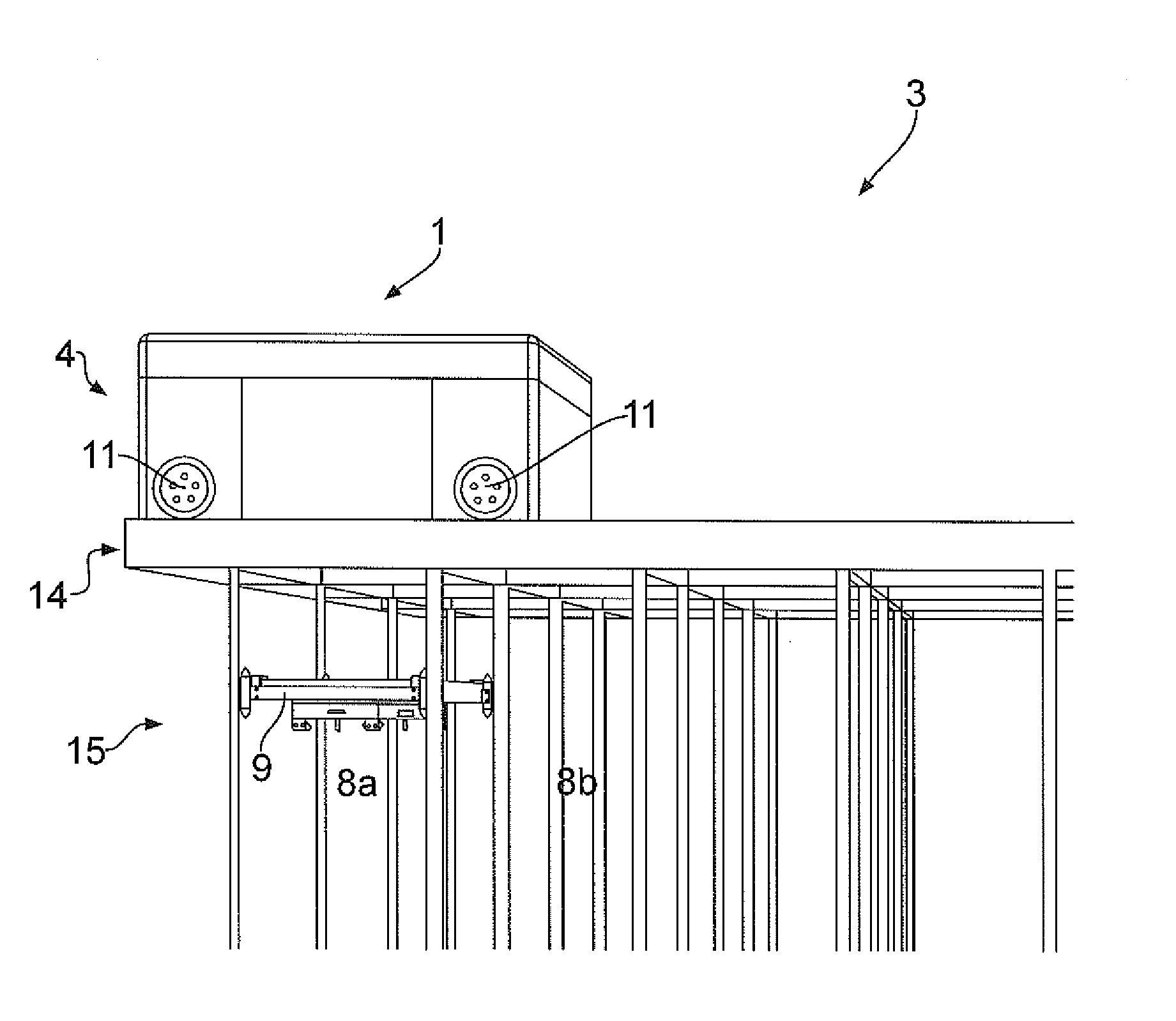
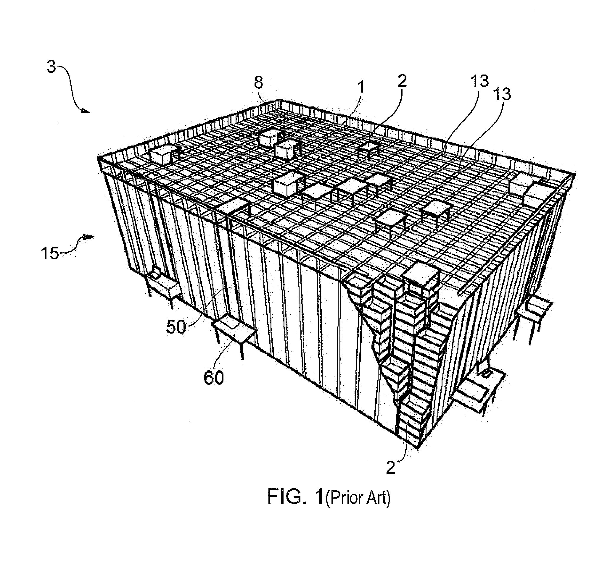
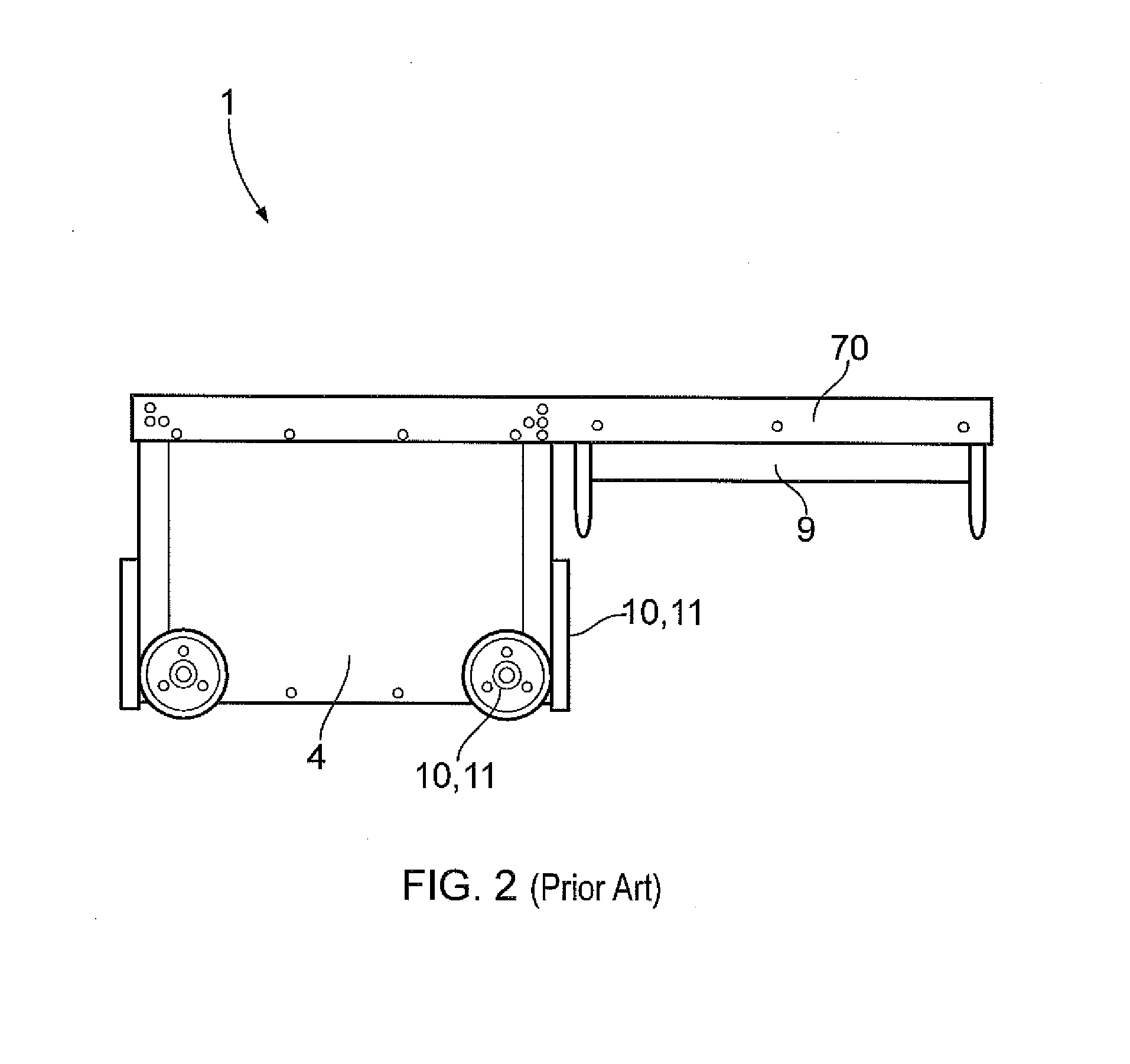
[0029]FIG. 1 is a schematic, partly cut perspective view of a storage system according to the prior art, and FIG. 2 is a sectional view of a corresponding prior art robot. Both figures have already been referred to earlier in the text. FIGS. 3 and 4 gives a perspective view in two different angles of the inventive robot 1 comprising a rectangular vehicle body or framework 4 with a cavity 7 centrally arranged within the body 4, a top lid 72 covering the top part of the body 4, a first set of four wheels 10 mounted inside the cavity 7 and in parallel to the interior walls of the body 4 and a second set of four wheels 11 mounted in parallel to the exterior walls of the body 4. The first and second set of wheels 10,11 are oriented perpendicular to each other. Further, the vehicle body 4 also includes side parts 5,5a,5b arranged on both sides of the cavity 7 along at least one of the robots 1 direction of movements. For the sake of clarity a Cartesian coordinate system is shown with its ...


PUM


Abstract

A remotely operated vehicle or robot for picking up storage bins from a storage system includes a vehicle body, which includes a first section for storing vehicle driving means and a second section for receiving any storage bin stored in a storage column within the storage system, a vehicle lifting device in order to lift the storage bin into the second section, a first and a second set of vehicle rolling means allowing movement of the vehicle along a first and a second direction perpendicular to the first direction, respectively, within the storage system. The second section includes a cavity arranged centrally within the vehicle body. This cavity has at least one bin receiving opening facing towards the underlying storage columns At least one of the two sets of vehicle rolling means is arranged fully within the vehicle body.

Description

[0001]FIELD OF INVENTION[0002]The present invention relates to a remotely operated vehicle for picking up storage bins from a storage system and to a storage system using the inventive vehicle.BACKGROUND OF INVENTION[0003]A remotely operated vehicle for picking up storage bins from a storage system is known. A detailed description of a relevant prior art storage system is given in WO 98 / 49075. Further, details of a prior art vehicle being suitable for such a storage system is disclosed in Norwegian patent NO317366. More specifically the prior art storage system comprises a three dimensional storage grid containing storage bins that are stacked on top of each other to a certain height. The storage grid is normally constructed as aluminum columns interconnected by top rails. A number of remotely operated vehicles, or robots, are arranged on the top rails. Each vehicle is equipped with a lift for picking up, carrying, and placing bins that are stored inside the storage grid.[0004]Such ...

Claims


Application Information

Patent Timeline
IPC IPC(8): B65G1/04
CPCB65G1/0464B65G1/0492G06Q10/087B65G1/0478B65G1/137B66F9/063G06Q10/00G06Q10/08B65G2201/025G05B19/41895G05D2201/0216B66F9/07B65G1/06B65G1/065G05D1/0022B65G1/00B65G1/0407B65G1/1371G06K17/00B66F9/06
Inventor HOGNALAND, INGVAR
Owner AUTOSTORE TECH AS
Why Eureka
Try Eureka