Water filter cartridge and manifold head seal

a technology of manifold and filter cartridge, which is applied in the direction of filtration separation, separation process, instruments, etc., can solve the problems of leakage testing of each filter cartridge, release defeating the use of rapid pressurization, and current filters that contain carbon cannot be tested in this fashion

Active Publication Date: 2015-10-29
BAIRD MICAHEL T
View PDF1 Cites 24 Cited by
  • Summary
  • Abstract
  • Description
  • Claims
  • Application Information

AI Technical Summary

Benefits of technology

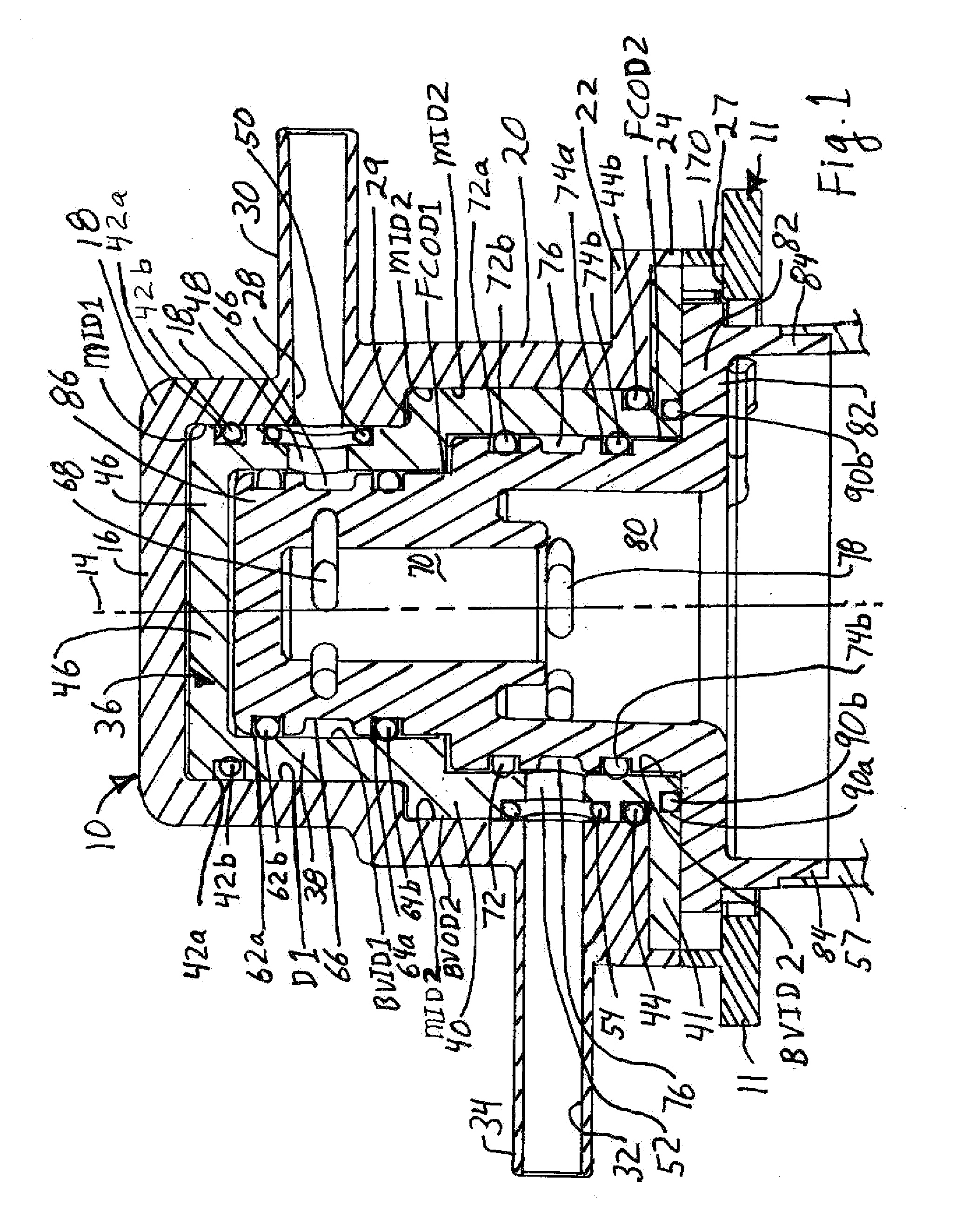
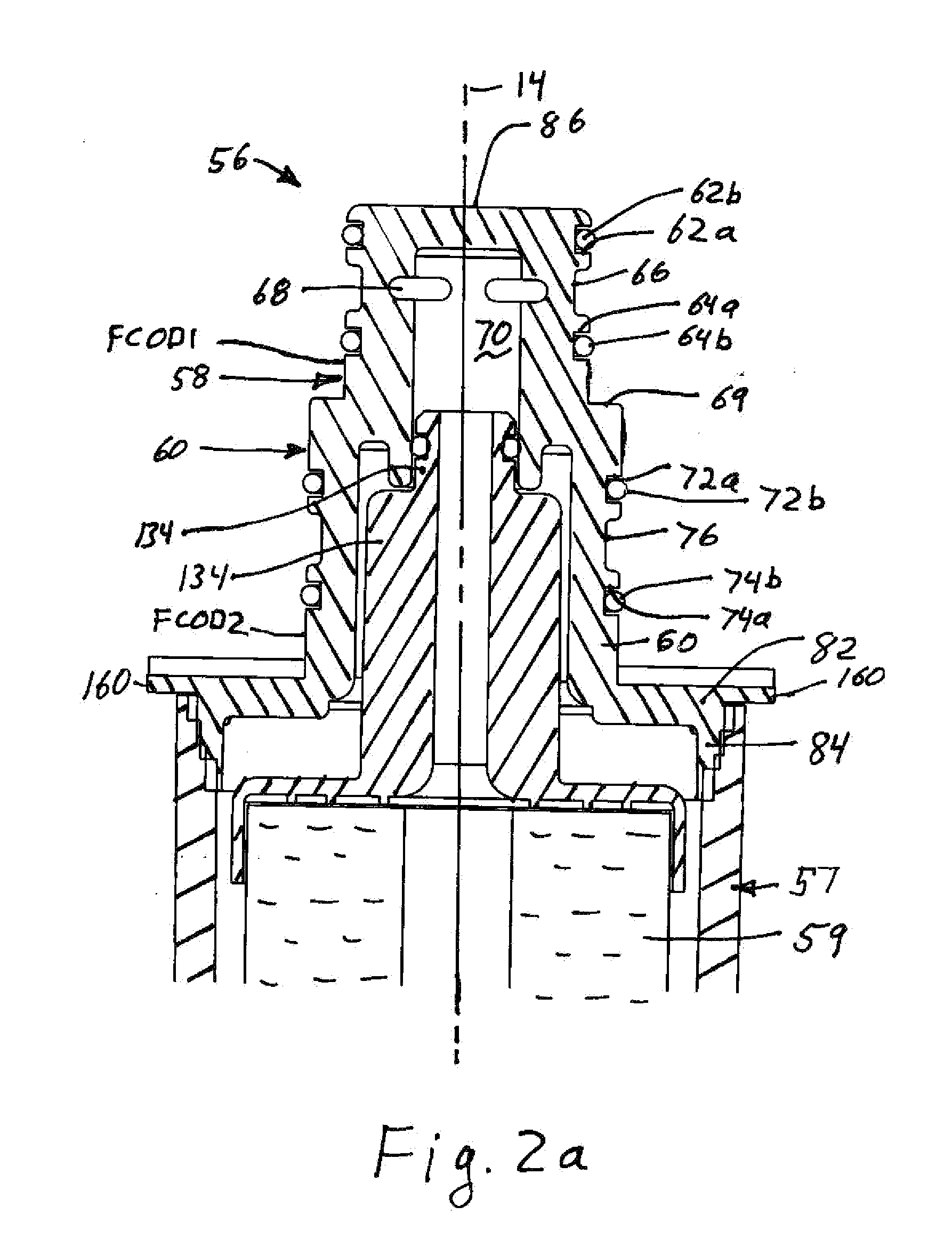
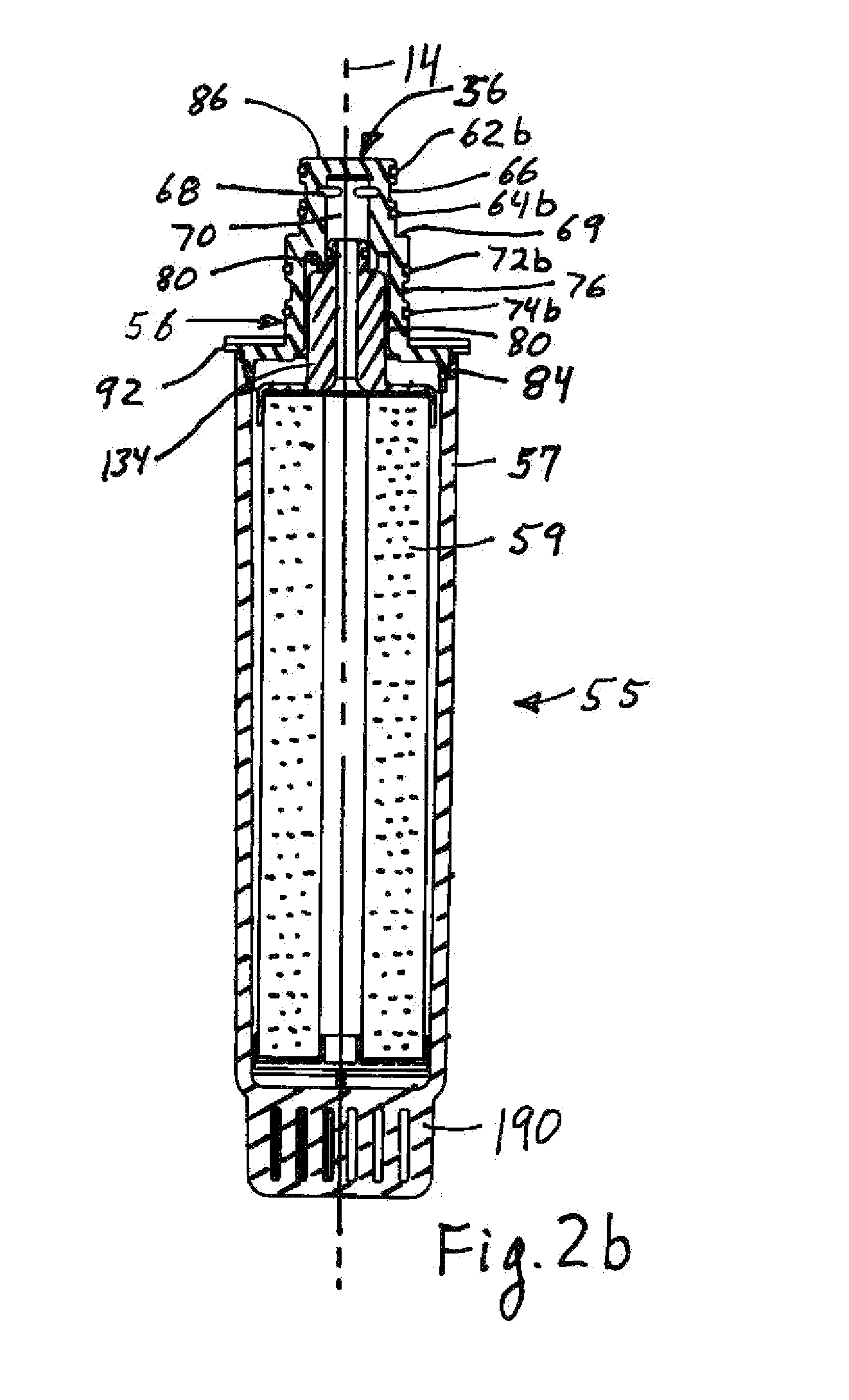
[0012]A manifold head has a barrel valve into which is inserted a filter cap configured to be placed on the end of a filter cartridge having a housing with a filter element and internal passages configured to convey unfiltered fluid from an inlet passage through the manifold head and filter cap and through the filter element and provide filtered fluid to filter cap at an outlet in fluid communication with an outlet passage through the barrel valve and manifold head. The manifold head, barrel valve and filter cap have a common longitudinal axis preferably extending along a length of the cartridge. The engagement between the manifold head and the filter cap is configured so that the inlet and outlet flow paths through the manifold head, barrel valve and filter cap are in a radial plane. The filter cap is removably inserted into the barrel valve and during filtering use the fluid path between the barrel valve and the filter cap are further contained in a generally cylindrical, annular space t

Problems solved by technology

Further, because the seal arrangement and flow arrangement reduces axial force on the filter and filter nozzle, it is possible to leak test each filter cartridge before use.
Current filters that contain carbon ca

Method used


Image

  • Water filter cartridge and manifold head seal
  • Water filter cartridge and manifold head seal
  • Water filter cartridge and manifold head seal

Examples


Embodiment Construction

[0072]Referring to FIGS. 1-3, 6-7 and 11-12, a filter manifold head 10 is connected to a manifold base 11. The manifold head 10 has a sidewall 12 (FIGS. 11-12) encircling longitudinal axis 14 and connected to end wall 16 to close one end of the manifold head and form a hollow interior with an opening opposite end wall 16. The sidewall 12 may have a first generally cylindrical portion 18 adjacent the end wall 16 and having a first interior diameter MID1 (Manifold Inner Diameter 1). The sidewall 12 may have a second portion 20 adjoining the first portion and closer to the open end of the manifold head with the second portion 20 having a second interior diameter MID2 (Manifold Inner Diameter 2). Advantageously MID2 is greater than MID1 and the end wall 16 is orthogonal to the longitudinal axis 14. Advantageously an outwardly extending mounting flange 22 encircles at least part of and preferably the entire open end of the manifold head 10. The mounting flange 22 advantageously has a ski...


PUM

PropertyMeasurementUnit
Timeaaaaaaaaaa
Lengthaaaaaaaaaa
Thicknessaaaaaaaaaa

Abstract

A water filter cartridge has a cap with radially oriented first and second (either inlet or outlet) flow channels on first and second generally cylindrical portions. First and second seals encircle the first flow channel on the first portion and third and fourth seals encircle the second flow channel on the second portion. The second and third seals form a void volume during use which may be accessed by a vent path to eliminate moisture or to test for or indicate leaks. The radial flow paths reduce axial, push out forces on the filter cartridge and allow smaller locking tabs to be used. The first seal forms a top void volume during use which may be accessed by a vent path to eliminate moisture or to test for or indicate leaks.

Description

CROSS-REFERENCE TO RELATED APPLICATIONS[0001]The application claims the benefit under 35 U.S.C. §119(e) to Provisional Patent Application No. 61 / 983,392 filed Apr. 23, 2014 and Provisional Patent Application No. 62 / 020,218 filed Jul. 2, 2014 the entire contents of which are incorporated herein by reference.BACKGROUND[0002]The present invention relates generally to water filter cartridges used in home and business water filter systems, and optionally used in commercial applications. Current filter systems have a manifold head with a manifold head inlet port connected to a source of water and a manifold head outlet port connected to a dispenser for the filtered water, such as a household refrigerator, or an apparatus using filtered water such as a coffee maker. The manifold head typically has a generally cylindrical, cup shaped interior, and often has a single, uniform diameter or two different diameters forming a stepped configuration. A removable filter cartridge has a cartridge hea...

Claims


Application Information

Patent Timeline
IPC IPC(8): C02F1/00G01M3/04
CPCC02F1/003C02F2103/02C02F2307/10G01M3/04C02F2201/006G01M3/26B01D35/30B01D2201/301C02F2201/004C02F2201/005
Inventor BAIRD, MICHAEL T.PARMLEY, RANDY L.JULOS, JOHN J.
Owner BAIRD MICAHEL T
Why Eureka
Try Eureka