
Circuit breakers with clock spring drives and/or multi-lobe drive cams and related actuators and methods

a technology of clock spring drive and cam, which is applied in the direction of snap-action arrangement, switch power arrangement, high-tension/heavy-dress switch, etc., can solve the problem of potential undue stress on the shaft bearing

Active Publication Date: 2015-10-29
EATON INTELLIGENT POWER LIMITED
View PDF6 Cites 18 Cited by
  • Summary
  • Abstract
  • Description
  • Claims
  • Application Information

AI Technical Summary

Benefits of technology

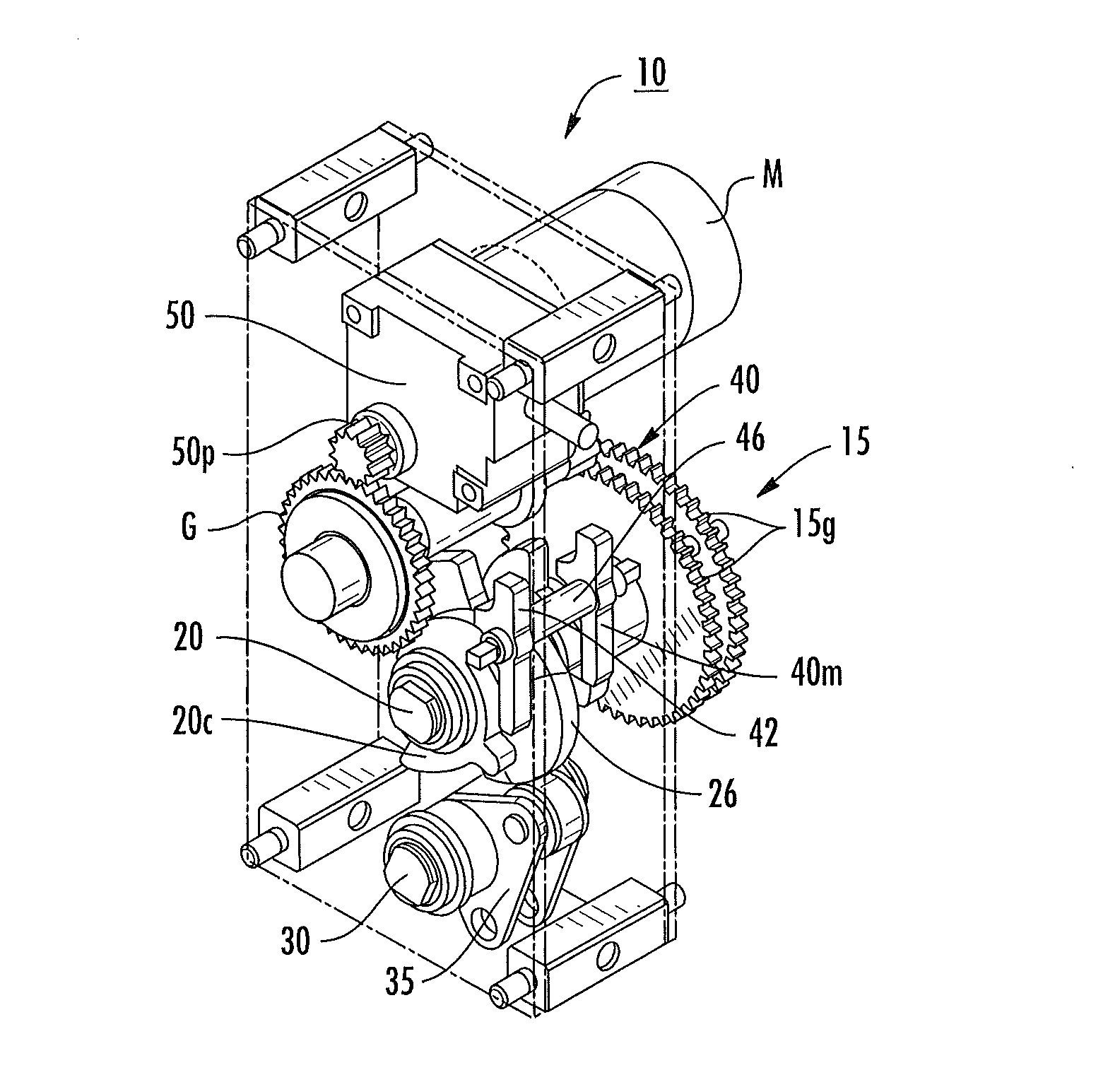
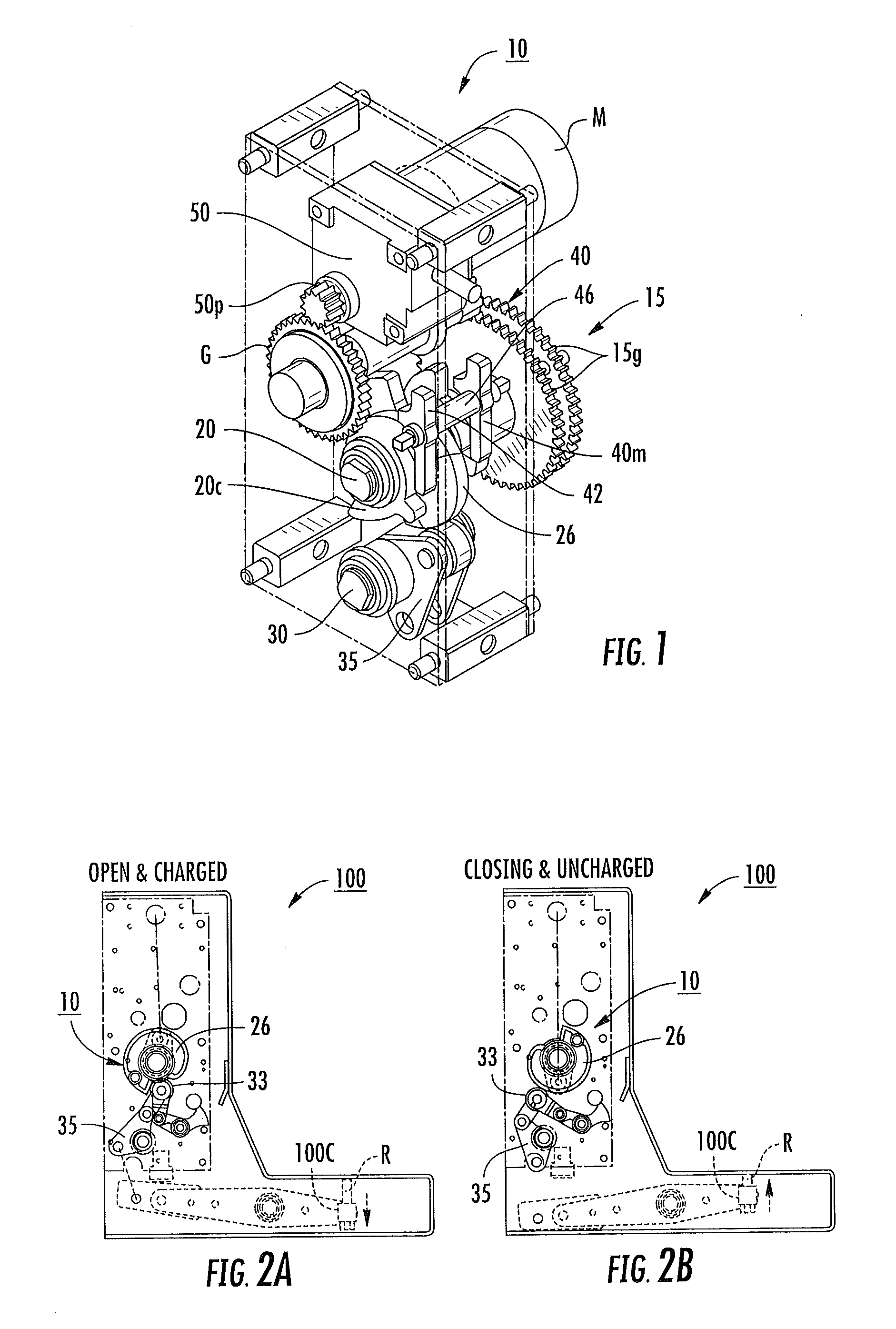
The present invention relates to operator mechanisms for electrical circuit breakers or electrical switching apparatuses. The mechanisms include a spring-actuated drive cam with a clock spring that is held on a cam shaft and a follower that directs an actuator to open or close a mobile contact to maintain open and closed energy status of the electrical circuit. The at least one clock spring can be a closing spring or a spring that is used to close the circuit breaker. The actuator can be an electric motor with a clutch and a main shaft that causes the actuator to open or close the electrical circuit. The invention allows for modular build configurations and can be used across different rated circuit breakers. The drive cam can have a perimeter with a plurality of lobes and valleys that define the opening and closing positions of the circuit breaker. The invention provides a scalable and versatile solution for electrical circuit breaker operator mechanisms.

Problems solved by technology

Unfortunately, conventional compression closing springs may apply a relatively large spring force that can present operational issues, e.g., the closing spring force may push up on a main shaft when it is charged and put a large moment on the shaft with potentially undue stress on shaft bearings and / or misalignment in operational components such as a frame in communication with the shaft.

Method used


Image

  • Circuit breakers with clock spring drives and/or multi-lobe drive cams and related actuators and methods
  • Circuit breakers with clock spring drives and/or multi-lobe drive cams and related actuators and methods
  • Circuit breakers with clock spring drives and/or multi-lobe drive cams and related actuators and methods

Examples


Embodiment Construction

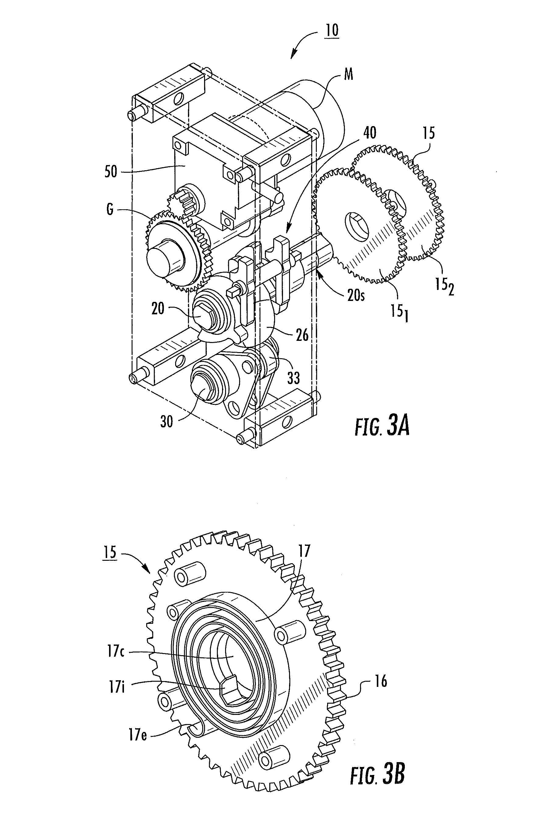
[0007]Embodiments of the present invention are directed to operator mechanisms with spring-actuated drives that include at least one clock spring held on a cam shaft with a drive cam configured to close a circuit breaker.

[0008]The at least one clock spring can be configured as a closing spring of the operator mechanism that is configured to drive a pinion associated with an electric motor and that can be used without requiring a compression closing spring.

[0009]Embodiments of the invention are directed to actuator devices that include at least one clock spring comprising a disc shaped body with gear teeth and a spiral spring, a cam shaft holding the at least one clock spring with an inner end portion of the spiral spring attached to the cam shaft, and a drive cam held by the cam shaft adapted to be in communication with a follower that is mechanically linked to a circuit interrupter.

[0010]The actuator devices can direct an actuator to open or close a mobile contact to maintain open ...


PUM


Abstract

Spring operated actuator devices for an electrical circuit breaker and / or electrical switching device include at least one clock spring comprising a disc shaped body with gear teeth and a spiral spring, a cam shaft holding the at least one clock spring with an inner end portion of the spiral spring attached to the cam shaft, and a drive cam held by the cam shaft adapted to be in communication with a follower that directs an actuator to open or close a mobile contact to maintain open and closed energy status of the electrical circuit. The at least one clock spring is configured as a closing spring of the spring operated actuator.

Description

FIELD OF THE INVENTION[0001]The present invention relates to operator mechanisms for circuit breakers.BACKGROUND OF THE INVENTION[0002]Circuit breakers are one of a variety of overcurrent protection devices used for circuit protection and isolation. The circuit breaker provides electrical protection whenever an electric abnormality occurs.[0003]In a power transmission or distribution network, switching apparatuses are incorporated into the network to provide automatic protection in response to abnormal load conditions or to permit opening or closing (switching) of sections of the network. The switching apparatus may therefore be called upon to perform a number of different operations such as interruption of terminal faults or short line faults, interruption of small inductive currents, interruption of capacitive currents, out-of-phase switching or no-load switching, all of which operations are well known to a person skilled in the art.[0004]One type of circuit breaker is a vacuum ci...

Claims


Application Information

Patent Timeline
IPC IPC(8): H01H3/30H01H3/38
CPCH01H3/3015H01H3/3026H01H3/3031H01H2235/016H01H3/38H01H2235/01H01H3/3042H01H3/42H01H33/666
Inventor YANG, CHAODING, CAIYINGYU, LIBRIGGS, ROGERDEVRIES, WILBERT ARTHUR HENRIK
Owner EATON INTELLIGENT POWER LIMITED
Learn More