
Ethernet poe to USB adapter device

Inactive Publication Date: 2015-10-29
PAVLOV MEDIA
View PDF3 Cites 21 Cited by
  • Summary
  • Abstract
  • Description
  • Claims
  • Application Information

AI Technical Summary

Benefits of technology

The invention provides a way to convert IEEE 802.3af or 802.3at compliant PoE Ethernet RJ-45 connector's voltage and data to standard Type A USB 3.0 connector's correct voltage and bi-directional data. This is done by using a small enclosure with input and output connectors at opposite ends. The system reduces the standard PoE voltage of 36-72 VDC to 5 VDC to meet the requirement of 25.5 watts of output power. The invention is useful when integrating into smaller devices like tablets.

Problems solved by technology

The rapid explosion of devices such as tablets present some problems when mounting them as fixed devices and providing power and data to the device.

Method used


Image

  • Ethernet poe to USB adapter device
  • Ethernet poe to USB adapter device
  • Ethernet poe to USB adapter device

Examples


Embodiment Construction

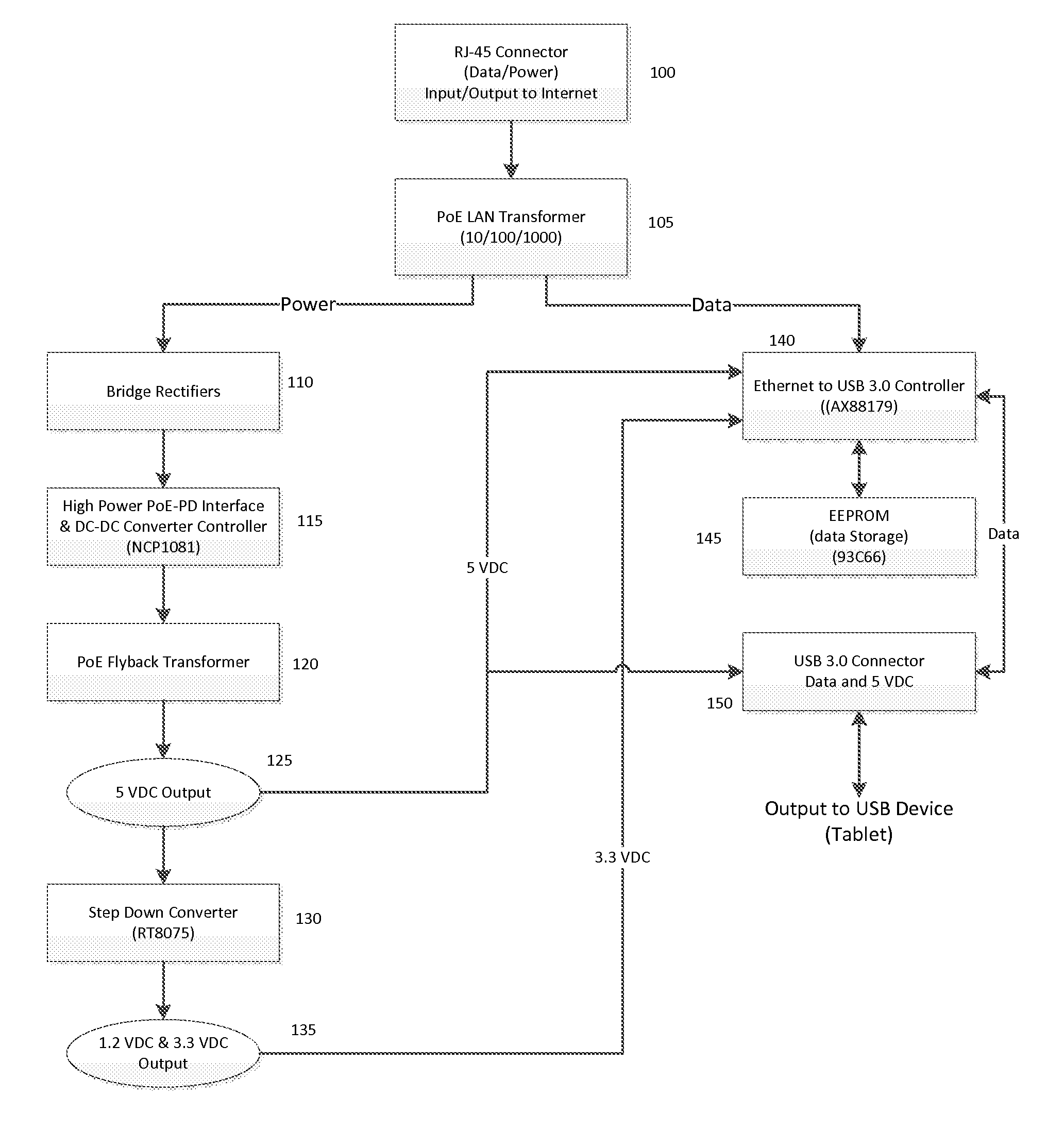
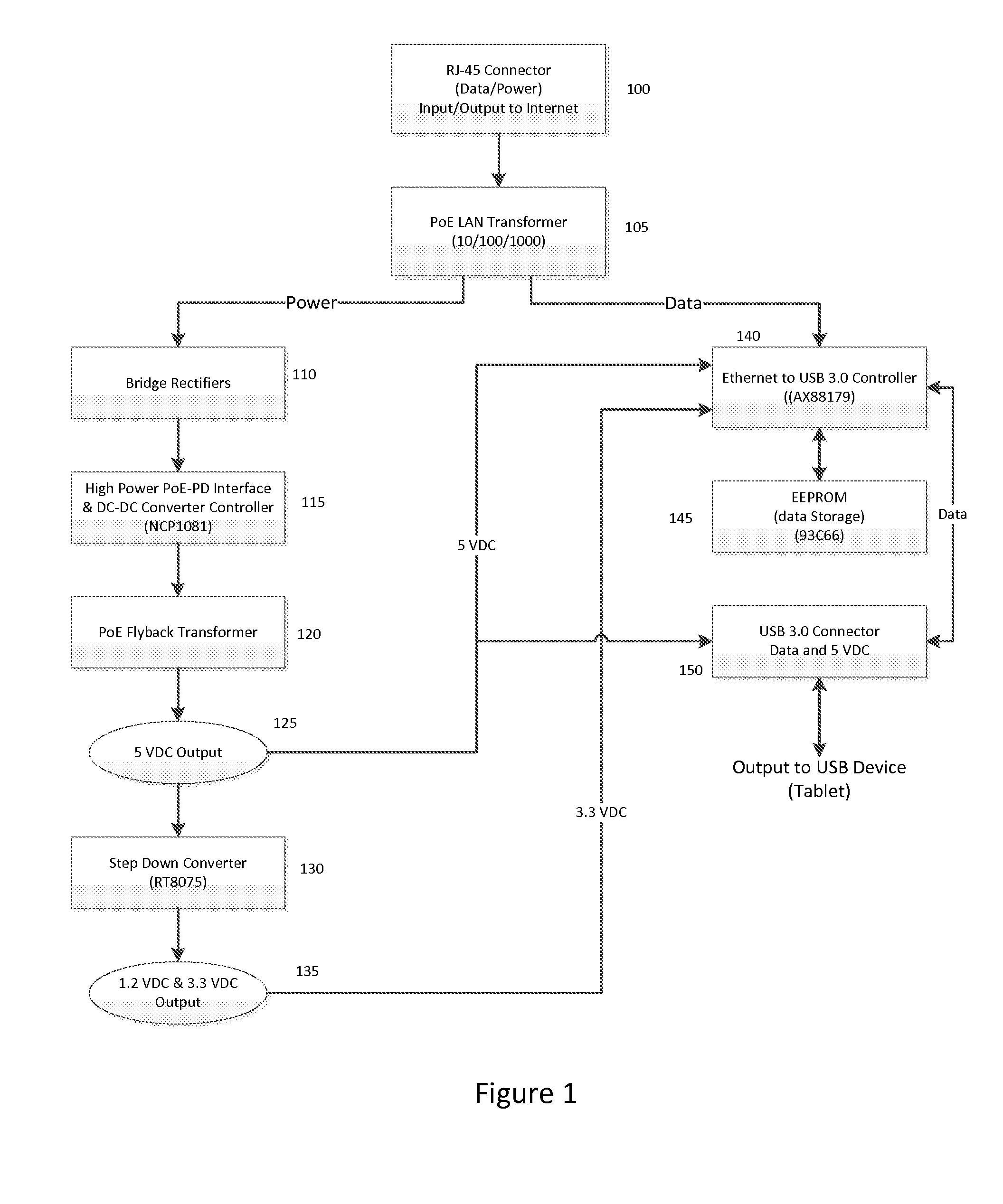
[0006]Referring to FIG. 1, a conventional PoE signal containing both data and AC power is supplied to the system through an RJ-45 connector (100). The data portion of the signal can be as fast as 1 Gigabit per second (Gbps). The combined data and power are then run through a PoE LAN transformer (105), splitting the AC power from the data signal.

[0007]The PoE LAN transformer provides coupling and impedance matching between the Ethernet connection (100) and the Ethernet to USB 3.0 Controller IC (140) and has low crosstalk.

[0008]In an embodiment, the AC power is converted to DC through, for example, a pair of bridge rectifiers (110) and, in some embodiments, a voltage regulator that provides a stable, polarity insensitive, DC voltage input to a DC-DC converter controller chip (115). In an embodiment, the DC-DC converter is an IEEE 802.3at compliant switching power supply that can supply up to 40 watts of power at the output, such as the NCP1081 device available from On Semiconductor. T...


PUM


Abstract

A PoE to USB adapter comprises the electronic circuitry to take the incoming PoE signal and extract 5 volts DC from the power segment of the signal and provide that voltage, along with the bi-directional data contained within the PoE signal to a standard USB 3.0 connector.

Description

FIELD OF THE INVENTION[0001]The present invention relates generally to the field of internet connectivity, and more particularly relates to circuitry for extracting and providing a 5 volt DC USB power source from an existing Power over Ethernet (PoE) voltage source, while passing through the power and Ethernet bi-directional data signal on a USB 3.0 connector at up to 1 Gbps.BACKGROUND OF THE INVENTION[0002]The rapid explosion of devices such as tablets present some problems when mounting them as fixed devices and providing power and data to the device. In normal operation the tablet would have a separate power supply to charge an internal battery requiring a wall outlet to provide the AC power. The Ethernet connection is usually made via a wireless connection. This invention allows the tablet to be permanently mounted to a wall or other surface for security and provide the power and data signal through a single connector. In areas that do not have wireless Ethernet available, a wir...

Claims


Application Information

Patent Timeline
Patent Type & Authority Applications(United States)
IPC IPC(8): H02J13/00G06F1/26H02J3/00H04L12/40
CPCH02J13/0096H02J3/00G06F1/266H04L12/40045
Inventor SCIFRES, MARK
Owner PAVLOV MEDIA
Learn More