Vent assembly and method for a digital valve positioner

a digital valve positioner and vent assembly technology, applied in the field of digital valve positioners, can solve the problems of affecting the operation of the internal devices affecting the operation of the digital valve positioner, and affecting the sound of the exhaust medium flowing, so as to reduce the sound of the vent assembly and reduce the sound of the exhaust medium. the effect of flowing

Active Publication Date: 2015-11-05
FISHER CONTROLS INT LLC
View PDF29 Cites 18 Cited by
  • Summary
  • Abstract
  • Description
  • Claims
  • Application Information

AI Technical Summary

Benefits of technology

[0008]According to another exemplary aspect of the present disclosure, a digital valve positioner for use with an actuator is disclosed, the digital valve positioner comprising a housing, at least one exhaust port opening formed in the housing, and a vent assembly operatively coupled to the at least one exhaust port opening. The vent assembly includes a body operatively coupled to the at least one exhaust port opening, the body including a bore, and a valve seat surrounding the bore. A check valve is disposed within the bore, the check valve arranged to shift from a closed position seated against the valve seat to an open position disposed away from the valve seat when an exhaust medium flows through the at least one exhaust port opening. In addition, a cap is removably secured to the body, the cap having a plurality of barriers extending therefrom and disposed around the check valve to enclose the check valve, the cap and the plurality of barriers arranged to prevent an external medium from entering the check valve and to provide a tortuous flow path for the exhaust medium reducing sound through the vent assembly.
[0009]According to a further exemplary aspect of the present disclosure, a vent assembly for a digital valve positioner operatively coupled to an actuator is disclosed. The vent assembly comprises a body having an inlet, an outlet, a bore disposed between the inlet and the outlet, a plurality of apertures surrounding the bore, and a valve seat surrounding the plurality of apertures. The body is adapted to be opera...

Problems solved by technology

Such larger porting, however, can lead to a greater chance for dirt and moisture and any other external medium in the environment to migrate into the digital valve positioner, which can adversely affect the operation of internal...

Method used


Image

  • Vent assembly and method for a digital valve positioner
  • Vent assembly and method for a digital valve positioner
  • Vent assembly and method for a digital valve positioner

Examples


Embodiment Construction

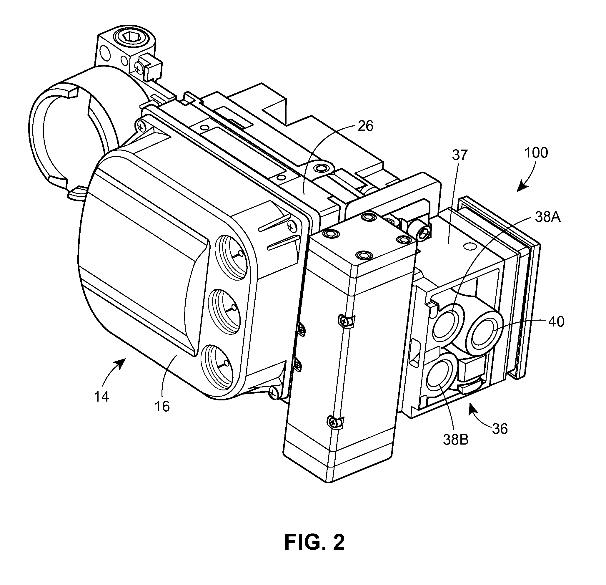
[0032]Generally, a digital valve positioner for use with an actuator is disclosed. The digital valve positioner includes a housing, at least one exhaust port opening formed in the housing, and a vent assembly operatively coupled to the at least one exhaust port opening. As explained in more detail below, the vent assembly both protects the exhaust port opening from the ingress of any external medium, such as dirt, moisture, rain, wind, hail or other external material in the environment, and reduces the noise levels generated by high flow of an exhaust medium through the exhaust port. The vent assembly achieves such benefits without affecting the flow capacity of the digital valve positioner.

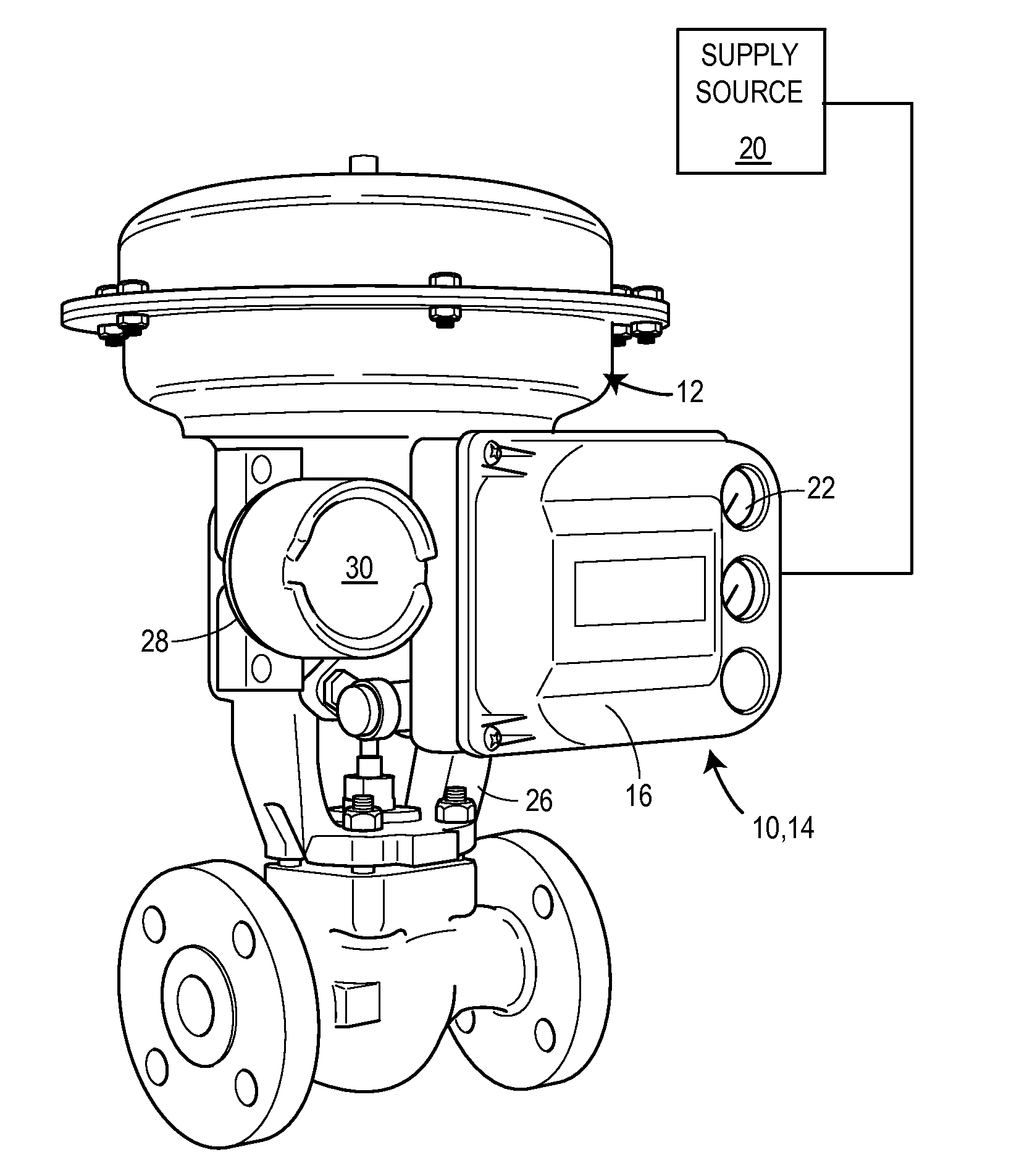
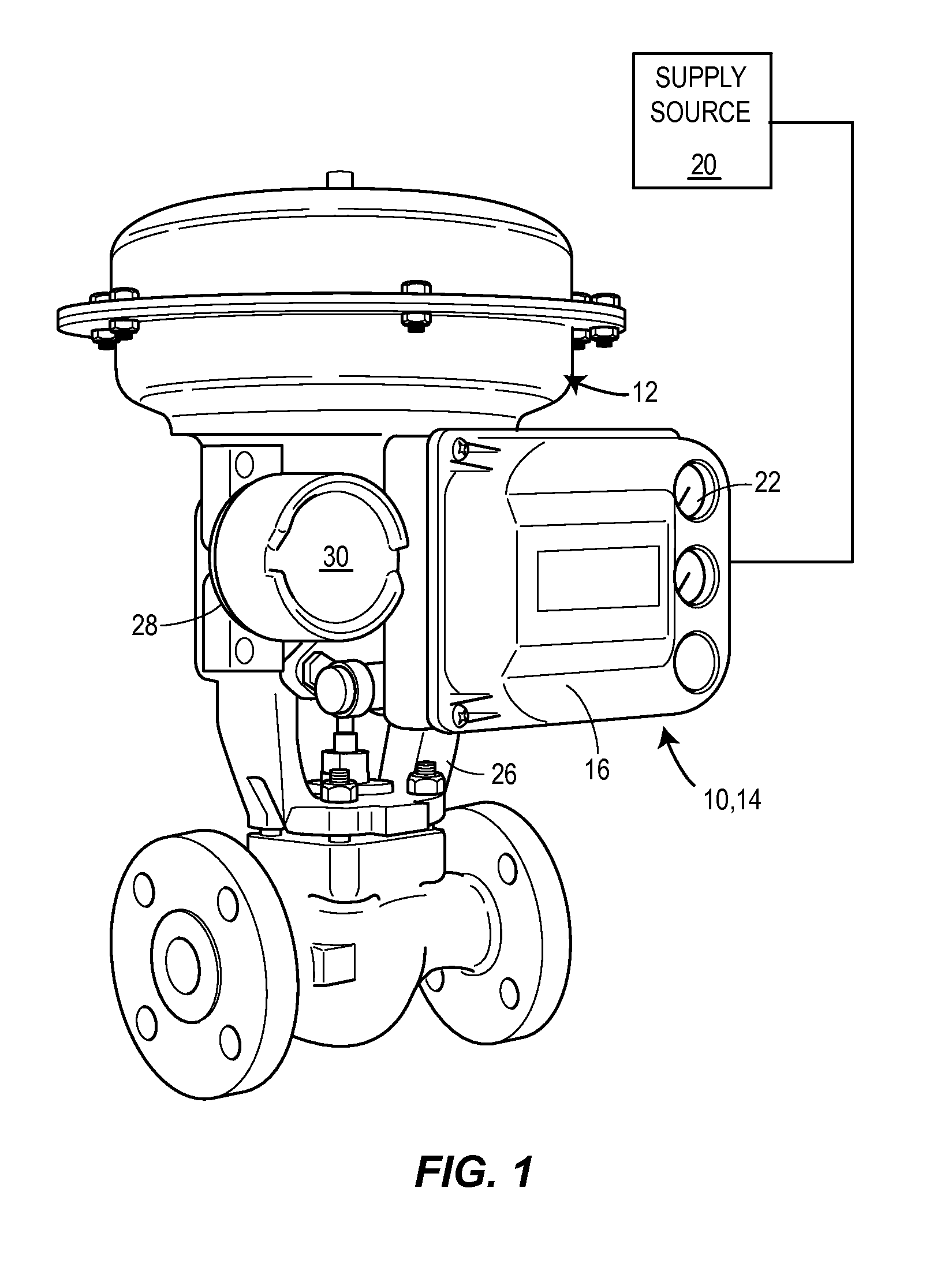
[0033]Referring now to FIG. 1, an exemplary field instrument 10 mounted to a valve actuator 12 is depicted. The field instrument 10 may be an electro-pneumatic field instrument, such as a digital valve positioner 14. The digital valve positioner 14 includes a main cover 16, a pneumatic relay asse...


PUM


Abstract

A digital valve positioner for use with an actuator. The digital valve positioner includes a housing, at least one exhaust port opening formed in the housing, and a vent assembly operatively coupled to the at least one exhaust port opening. The vent assembly includes a body having a bore, a valve seat surrounding the bore, and a check valve disposed within the bore. The check valve is arranged to shift from a closed position seated against the valve seat to an open position disposed away from the valve seat. A plurality of barriers is disposed around and positioned to enclose the check valve. The plurality of barriers is arranged to prevent an external medium from entering the check valve and to provide a tortuous flow path for the exhaust medium reducing sound through the vent assembly.

Description

FIELD OF THE DISCLOSURE[0001]The present invention relates generally to digital valve positioners, and, more specifically, to a vent assembly for a high capacity digital valve positioner.BACKGROUND OF THE DISCLOSURE[0002]Distributed process control systems, like those used in chemical, petroleum or other processes, typically include one or more process controllers communicatively coupled to one or more field devices via analog, digital or combined analog / digital buses. The field devices, which may be, for example, valves, valve positioners, e.g., digital valve positioners, and transmitters, e.g., temperature, pressure, level and flow rate sensors, are located within the process environment and perform process functions such as opening or closing valves and measuring process parameters. Smart field devices, such as the field devices conforming to the well known FOUNDATION® Fieldbus protocol may also perform control calculations, alarming functions, and other control functions commonl...

Claims


Application Information

Patent Timeline
IPC IPC(8): F16K15/00F16K47/04F16K31/12F15B21/044
CPCF16K15/00F16K31/12Y10T137/86485Y10T137/0324Y10T137/86324F16K47/04F16K31/02F16K47/08F16K15/148F15B21/008F15B5/006F15B21/044F15B2211/8616F16K15/14
Inventor WINKLER, RICHARD J.JUNK, KENNETH W.JELKEN, SHANNON E.ROESSLER, FRANCIS C.MACK, CHRISTOPHER J.
Owner FISHER CONTROLS INT LLC
Why Eureka
Try Eureka