X-ray shield grating and x-ray talbot interferometer including x-ray shield grating

a technology of x-ray shield and talbot, which is applied in the direction of material analysis using wave/particle radiation, instruments, and handling using diaphragms/collimeters, etc., can solve the problems of insufficient x-ray transmission contrast and the decrease of the amount of x rays which reach the detector

Active Publication Date: 2015-11-05
CANON KK
View PDF4 Cites 11 Cited by
  • Summary
  • Abstract
  • Description
  • Claims
  • Application Information

AI Technical Summary

Benefits of technology

[0012]An X-ray shield grating as disclosed herein includes a substrate on which a plurality of recessed portions are arranged, and metal that is arranged in each of the recessed portions. The substrate includes a bent region that is bent in an arrangement direction in which the plurality of recessed portions are arranged. A radius of curvature of the bent region is 200 millimeters or less. In the bent region, in a case where a maximum value of a width of a region sandwiched between two adjacent recessed portions of the plurality of recessed portions is less than or equal to three times a minimum value of the width of the region sandwiched between the two adjacent recessed portions, and in a case where a width of the substrate in an end portion of the bent region represents a shortest distance from the end portion to the metal when the end portion is part of the substrate, and represents 0 when the end portion is part of the metal, the width of the substrate in the end portion of the bent region being less than or equal to three times the minimum value.

Problems solved by technology

Therefore, an insufficient X-ray transmission contrast is obtained, and the amount of X rays which reach a detector decreases.

Method used


Image

  • X-ray shield grating and x-ray talbot interferometer including x-ray shield grating
  • X-ray shield grating and x-ray talbot interferometer including x-ray shield grating
  • X-ray shield grating and x-ray talbot interferometer including x-ray shield grating

Examples


example 1

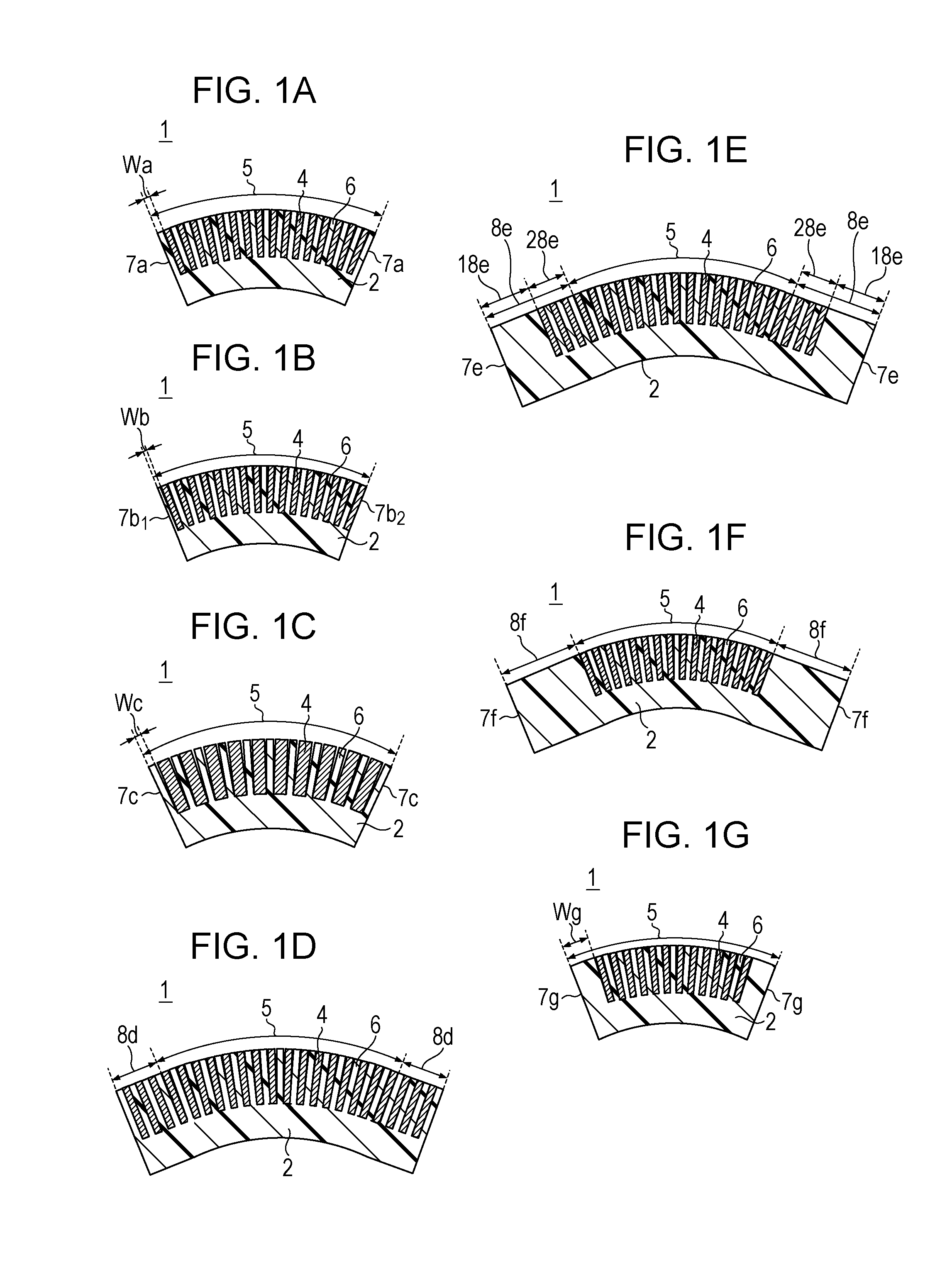
[0064]In Example 1, a more specific example of the X-ray shield grating 1 illustrated in FIG. 1A will be explained. In Example 1, a silicon substrate is used as a substrate, and gold is used as metal. A method for producing the X-ray shield grating 1 according to Example 1 will be explained with reference to FIGS. 4A to 4E and FIGS. 5A and 5B.

[0065]First, a substrate on which a plurality of recessed portions are arranged and metal is arranged in each of the recessed portions is prepared. Such a substrate may be obtained by performing steps, for example, illustrated in FIGS. 4A to 4D. The steps illustrated in FIGS. 4A to 4D will be explained below.

[0066]A silicon substrate with a diameter of 100 millimeters, a thickness of 200 micrometers, and a resistivity of 0.02 Ωcm is used as the substrate 2. By thermally oxidizing the silicon substrate at 1,050 degrees Centigrade for 75 minutes, thermal oxide films 20 of about 0.5 micrometers are formed on front and rear surfaces of the silicon ...

example 2

[0077]In Example 2, a specific example in which a substrate thicker than that used in Example 1 is used and an X-ray shield grating is bent in a method different from Example 1 will be explained. However, the other points are same as those in Example 1, and therefore a detailed explanation for those same points will be omitted.

[0078]Processing up to the step of cutting off end portions is performed in a manner similar to Example 1 with the exception that a silicon substrate with a thickness of 300 micrometers is used as the substrate 2, and the substrate 2 of 55 millimeters x 25 millimeters on which a plurality of recessed portions are arranged and gold is arranged in each of the recessed portions is obtained.

[0079]In Example 2, a step of bending the substrate whose end portions have been cut off, in the direction in which the plurality of recessed portions are arranged, is performed using supporting members 19 illustrated in FIGS. 6A and 6B. The supporting members 19 used in Exampl...

example 3

[0082]In Example 3, a specific example of the X-ray shield grating 1 illustrated in FIG. 1F will be explained. Example 3 is different from Example 1 in that the end portions of the substrate are cut off in such a manner that the width of the substrate in the end portions of the substrate is 10 millimeters in the step of cutting off the end portions of the substrate and that the substrate is bent in such a manner that not the entire substrate but only part of the substrate serves as a bent region. The other points are the same as those in Example 1, and a detailed explanation for those same points will be omitted.

[0083]In Example 3, a step of cutting off end portions of the substrate 2 is performed. In Example 3, end portions of the substrate are cut off in such a manner that the shortest distance from an end face of the substrate to metal is 10 millimeters, and the substrate 2 of 75 millimeters x 25 millimeters is thus obtained.

[0084]As illustrated in FIG. 7, by using the supporting...


PUM

PropertyMeasurementUnit
widthaaaaaaaaaa
radiusaaaaaaaaaa
thicknessaaaaaaaaaa

Abstract

An X-ray shield grating includes a substrate on which a plurality of recessed portions are arranged, and metal that is arranged in each of the recessed portions. The substrate includes a bent region that is bent in an arrangement direction in which the plurality of recessed portions are arranged. A radius of curvature of the bent region is 200 millimeters or less. In the bent region, a maximum value of a width of a region sandwiched between two adjacent recessed portions of the plurality of recessed portions and a width of the substrate in an end portion of the bent region are less than or equal to three times a minimum value of the width of the region sandwiched between the two adjacent recessed portions.

Description

BACKGROUND[0001]1. Field of the Invention[0002]The present disclosure relates to an X-ray shield grating and an X-ray Talbot interferometer including the X-ray shield grating.[0003]2. Description of the Related Art[0004]Gratings including a structural body having a periodic structure have been used as optical elements for various apparatuses. In particular, gratings formed of metal with a high X-ray absorptivity have been used as X-ray shield gratings for non-destructive tests for objects and in the area of medical care.[0005]As a use application of X-ray shield gratings, shield gratings in X-ray Talbot interferometers have been known. An imaging method using an X-ray Talbot interferometer (X-ray Talbot interference method) is one of methods for acquiring information of a subject by using a phase change of an X ray by the subject.[0006]An X-ray Talbot interference method will be briefly explained below. In an X-ray Talbot interferometer, spatially coherent X rays pass through a diff...

Claims


Application Information

Patent Timeline
Patent Type & Authority Applications(United States)
IPC IPC(8): G01N23/20G21K1/06
CPCG01N23/20075G21K2201/067G21K2201/064G21K1/067G21K1/06A61B6/4035A61B6/484
Inventor TESHIMA, TAKAYUKINAKAMURA, TAKASHISATO, GENTA
Owner CANON KK
Why Eureka
Try Eureka