
Epitaxial buffer layer for finfet source and drain junction leakage reduction

a buffer layer and drain junction technology, applied in the direction of semiconductor devices, transistors, electrical equipment, etc., can solve the problem of high cost of manufacturing soi finfets

Inactive Publication Date: 2015-11-05
IBM CORP +1
View PDF3 Cites 25 Cited by
  • Summary
  • Abstract
  • Description
  • Claims
  • Application Information

AI Technical Summary

Benefits of technology

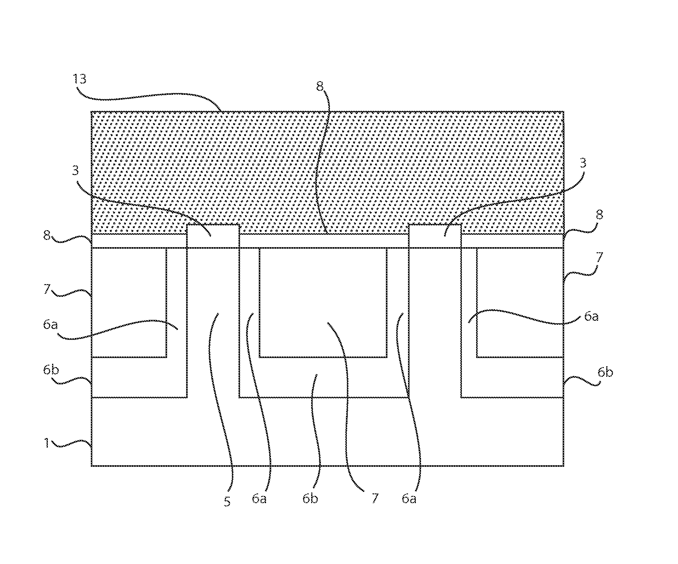
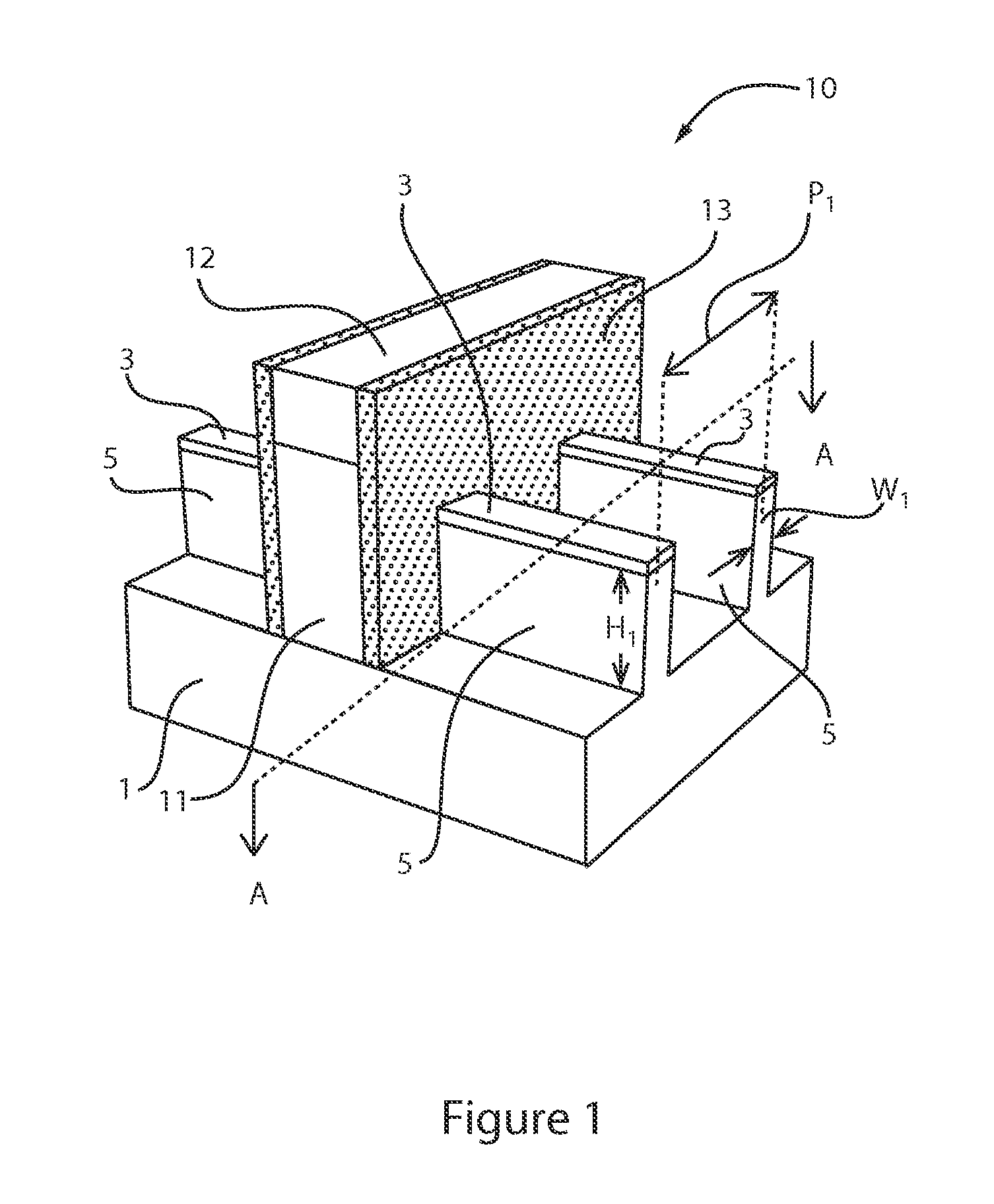
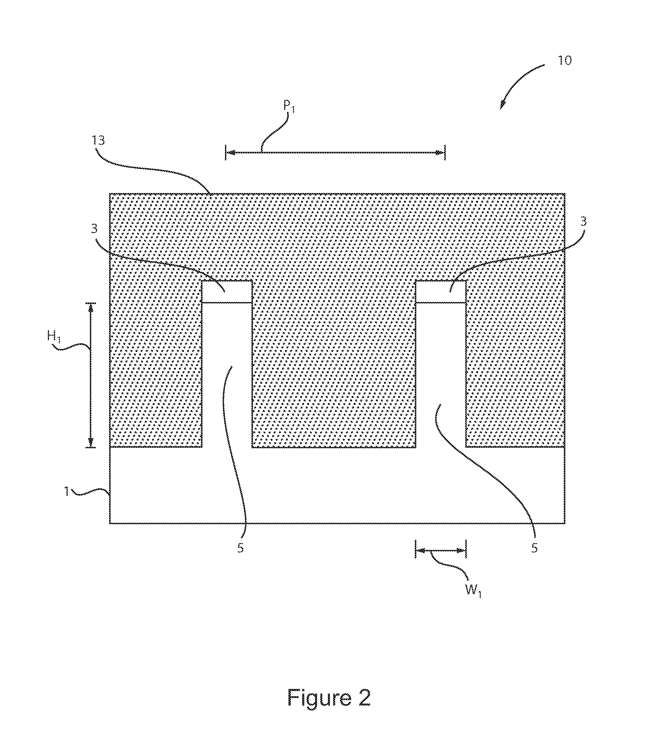
This patent describes a method and device for making a semiconductor device by forming fin structures from a bulk semiconductor substrate and then adding epitaxial semiconductor materials to create a source region and drain region. The method also includes forming a gate structure and a doped region with a gradual dopant concentration gradient. The technical effects of this patent are improved control over the dopant concentration and region, leading to better performance and reliability of semiconductor devices.

Problems solved by technology

However, the cost of manufacturing SOI finFETs can be high.

Method used


Image

  • Epitaxial buffer layer for finfet source and drain junction leakage reduction
  • Epitaxial buffer layer for finfet source and drain junction leakage reduction
  • Epitaxial buffer layer for finfet source and drain junction leakage reduction

Examples


Embodiment Construction

[0016]Detailed embodiments of the claimed structures and methods are disclosed herein; however, it is to be understood that the disclosed embodiments are merely illustrative of the claimed structures and methods that may be embodied in various forms. In addition, each of the examples given in connection with the various embodiments are intended to be illustrative, and not restrictive. Further, the figures are not necessarily to scale, some features may be exaggerated to show details of particular components. Therefore, specific structural and functional details disclosed herein are not to be interpreted as limiting, but merely as a representative basis for teaching one skilled in the art to variously employ the methods and structures of the present disclosure. For purposes of the description hereinafter, the terms “upper”, “lower”, “right”, “left”, “vertical”, “horizontal”, “top”, “bottom”, and derivatives thereof shall relate to the embodiments of the disclosure, as it is oriented ...


PUM


Abstract

A semiconductor device including a gate structure on a channel region portion of a fin structure, and at least one of an epitaxial source region and an epitaxial drain region on a source region portion and a drain region portion of the fin structure. At least one of the epitaxial source region portion and the epitaxial drain region portion include a first concentration doped portion adjacent to the fin structure, and a second concentration doped portion on the first concentration doped portion. The second concentration portion has a greater dopant concentration than the first concentration doped portion. An extension dopant region extending into the channel portion of the fin structure having an abrupt dopant concentration gradient of n-type or p-type dopants of 7 nm per decade or greater.

Description

RELATED APPLICATION INFORMATION[0001]This application claims priority to provisional application Ser. No. 61 / 987,180, entitled “EPITAXIAL BUFFER LAYER FOR FINFET SOURCE AND DRAIN JUNCTION LEAKAGE REDUCTION” that was filed on May 1, 2014, incorporated herein by reference.BACKGROUND[0002]1. Technical Field[0003]The present disclosure relates generally to semiconductor fabrication, and more particularly to structures and methods for forming fin field effect transistors (finFETs).[0004]2. Description of the Related Art[0005]With the continuing trend towards miniaturization of integrated circuits (ICs), there is a need for transistors to have higher drive currents with increasingly smaller dimensions. FinFET technology is becoming more prevalent as device size continues to shrink. However, the cost of manufacturing SOI finFETs can be high.SUMMARY[0006]In one embodiment, a method of forming a semiconductor device is disclosed that includes forming a fin structure from a bulk semiconductor...

Claims


Application Information

Patent Timeline
IPC IPC(8): H01L21/8234H01L29/78H01L29/08H01L29/66
CPCH01L21/823418H01L29/66795H01L29/66545H01L21/823431H01L21/823437H01L29/7816H01L29/7851H01L29/086H01L29/0878H01L29/0869H01L29/0886H01L29/66681H01L29/66H01L29/267H01L29/165H01L29/161H01L29/0847H01L29/7848H01L29/08H01L21/2252H01L21/324H01L29/0843H01L29/66636H01L27/0886H01L29/7833
Inventor GUO, DECHAOMOCHIZUKI, SHOGOSCHOLZE, ANDREASYEH, CHUN-CHEN
Owner IBM CORP
Learn More