
Belt conveyor for an automatic placement machine and automatic placement machine

Active Publication Date: 2015-11-12
ASM ASSEMBLY SYST GMBH & CO
View PDF20 Cites 1 Cited by
  • Summary
  • Abstract
  • Description
  • Claims
  • Application Information

AI Technical Summary

Benefits of technology

The present invention aims to improve the accuracy and affordability of belt conveyors and automatic placement machines. Specifically, it aims to provide a way to accurately position the pinwheel of a belt conveyor, while minimizing the cost and complexity of the sensor device required for this.

Problems solved by technology

Altogether, the method and the arrangement of the sensor arrangement for measuring the exact position of the pinwheel according to the prior art, in particular with respect to the mounting, thus represents a very laborious procedure.

Method used


Image

  • Belt conveyor for an automatic placement machine and automatic placement machine
  • Belt conveyor for an automatic placement machine and automatic placement machine
  • Belt conveyor for an automatic placement machine and automatic placement machine

Examples


Embodiment Construction

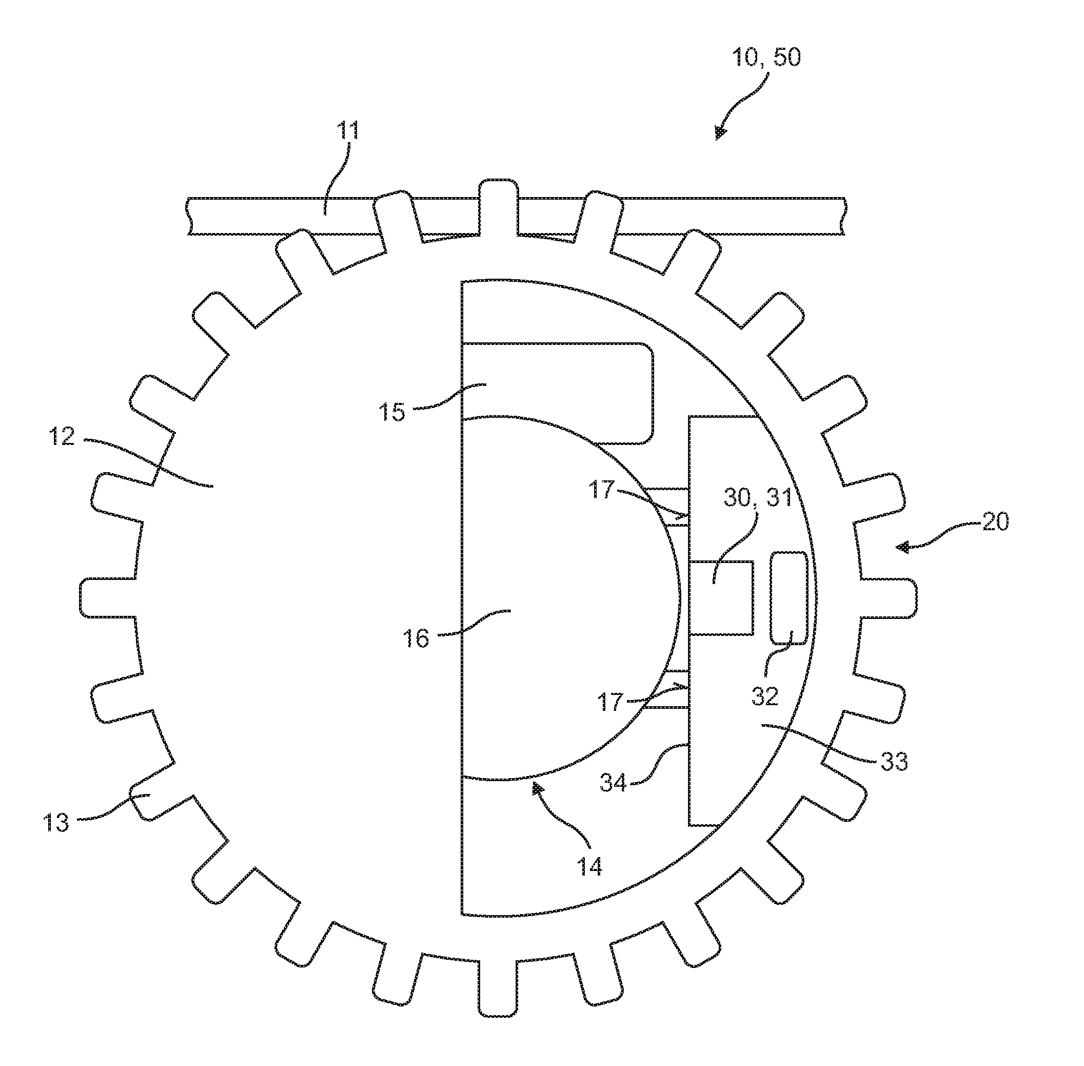
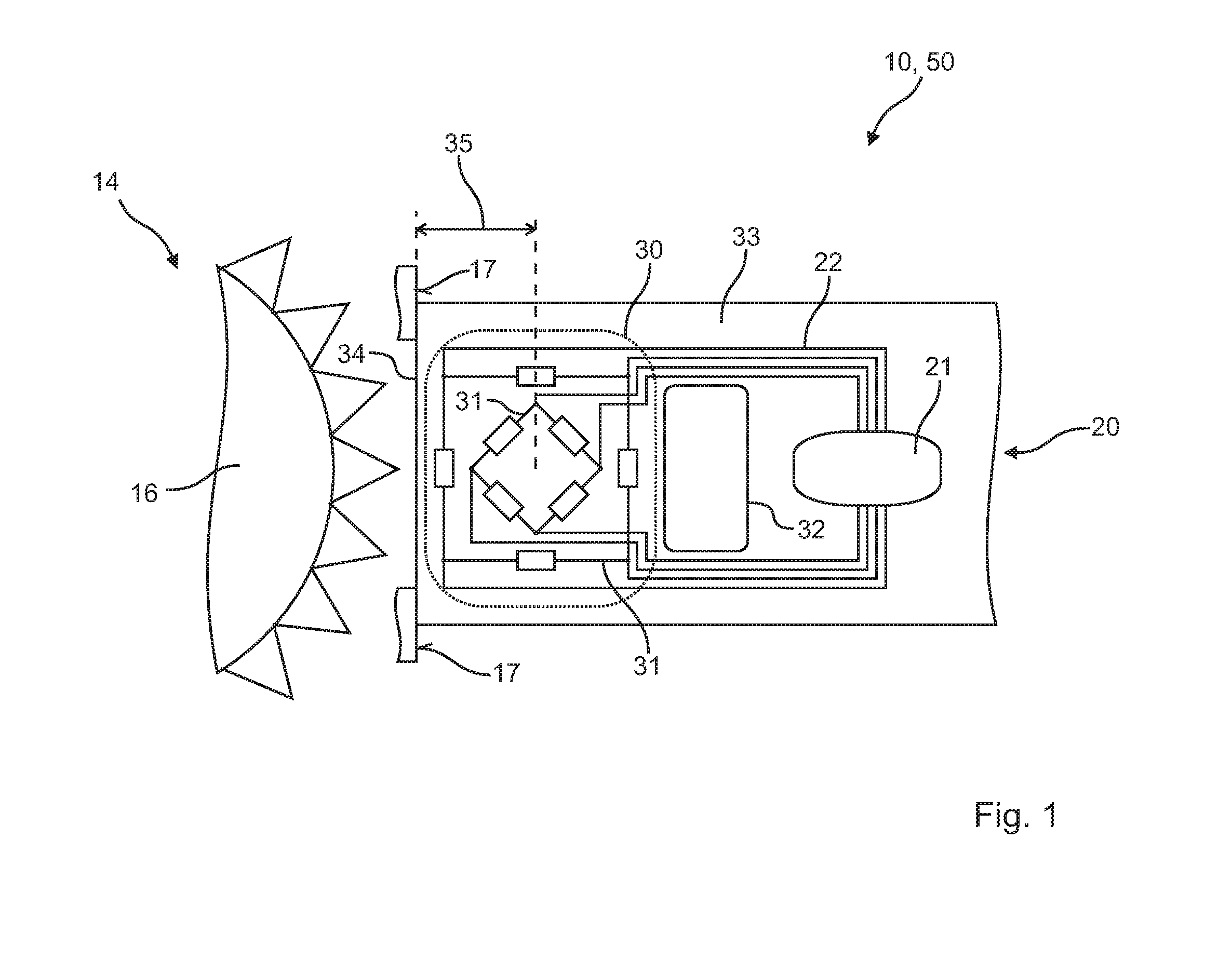
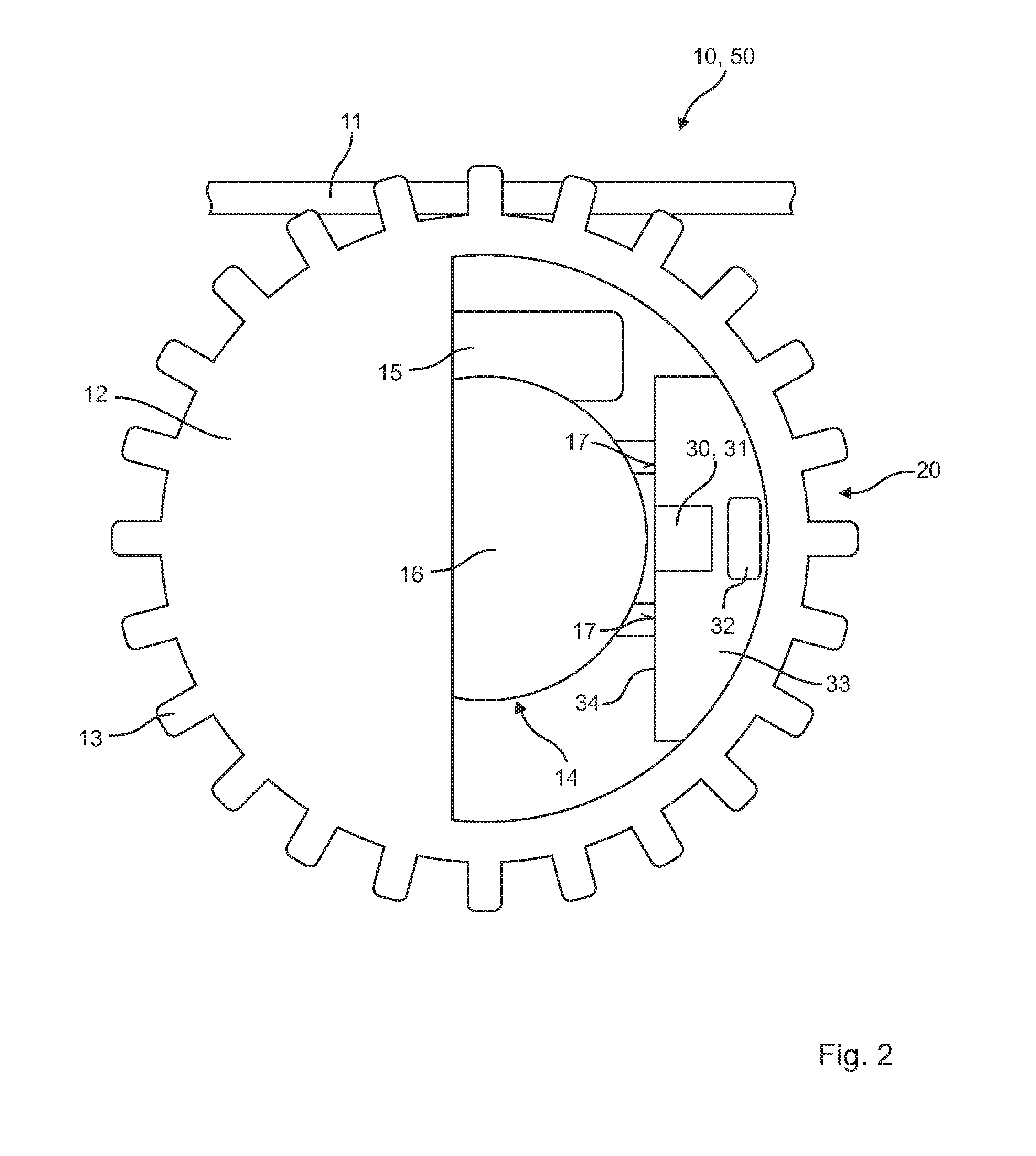
[0022]FIG. 1 shows part of a belt conveyor 10 according to the invention, which is fitted in an automatic placement machine 50. In particular, parts of a position-determining device 20 are shown. The position-determining device 20 has in particular here a first sensor device 30, which can be seen substantially as printed circuit board 33. Arranged on this printed circuit board 33 are two magnetoresistive sensor arrangements 31, which are respectively designed as Wheatstone bridge circuits. The two magnetoresistive sensor arrangements 31 are arranged here on the printed circuit board 33 in such a way that they are at a defined distance 35 from an edge 34 of the printed circuit board 33. It is provided here that the defined distance 35 is determined with an accuracy of preferably better than 0.050 mm. The two magnetoresistive sensor arrangements 31 are connected by electrical connections 22 to evaluation electronics 21 of the position-determining device 20. In addition, the two magnet...


PUM


Abstract

A belt conveyor (10) for an automatic placement machine (50) that includes at least a rotatably mounted pinwheel (12) for conveying a belt (11), a drive (14) with at least one gear wheel (16) for driving the pinwheel (12) and a position-determining device (20) for determining a rotational position of the pinwheel (12), the position-determining device (20) having a first sensor device (30) with at least one magnetoresistive sensor arrangement (31). The disclosure further includes an automatic placement machine (50) having at least one belt conveyor (10).

Description

CROSS-REFERENCE TO RELATED APPLICATIONS[0001]The present application claims benefit of German Patent Application No. 10 2014 106 543.3, filed May 9, 2014, the content of which is incorporated herein by reference.TECHNICAL FIELD OF THE INVENTION[0002]The present invention relates to a belt conveyor for an automatic placement machine, at least having a rotatably mounted pinwheel for conveying a belt, a drive with at least one gear wheel for driving the pinwheel and a position-determining device for determining a rotational position of the pinwheel, the position-determining device having a first sensor device with at least one magnetoresistive sensor arrangement. The invention also relates to an automatic placement machine, having at least one belt conveyor.BACKGROUND OF THE INVENTION[0003]In modern technology, electronic components that are arranged on printed circuit boards are often used. To be able to produce such printed circuit boards in large numbers, it is known to use automati...

Claims


Application Information

Patent Timeline
IPC IPC(8): B65G23/06G01D5/16
CPCB65G23/06G01D5/16B65G2203/043B65G2812/02128B65G2203/0266B65G2811/09B23P19/001G01B7/003H05K13/0419H05K13/082B65H20/20
Inventor KUHNAPFEL, RALFSTEIN, ARNO
Owner ASM ASSEMBLY SYST GMBH & CO
Learn More