Nozzle construction to facilitate its opening and enhance the flow of fuel through the nozzle

a technology of nozzles and nozzles, applied in the direction of liquid transfer devices, packaging goods types, liquid handling, etc., can solve the problems of difficult for handicapped and elderly to dispense fuel, and achieve the effects of convenient use and operation of nozzles, rapid filling, and less pressur

Active Publication Date: 2015-11-12
HUSKY CORP
View PDF4 Cites 2 Cited by
  • Summary
  • Abstract
  • Description
  • Claims
  • Application Information

AI Technical Summary

Benefits of technology

[0011]The concept of this invention is to provide for modifications to the operative components of a fuel dispensing nozzle, particularly with respect to the enhanced flow of fuel through the nozzle, and its poppet valve, and at the same time, furnishing means for lessening the pressure required to lift the poppet valve from its valve seat, requiring a much lesser force, to ease the use and operation of the nozzle, while dispensing fuel, particularly at a self-service dispenser. The first aspect of the improvements to the nozzle, is achieved through the use of a truncated poppet valve, one which when opened provides a greater space through which the fuel may flow, unobstructedly, to provide for a more rapid fill-up of the vehicle fuel tank, during dispensing. The second concept of the invention is to shift the fulcrum point at which the hand lever engages the bottom of the poppet stem, of the same poppet valve, to a position where greater leverage can be attained, thereby lessening the force required to open the poppet valve, in initiating fuel flow.
[0012]As known, the handle lever that is manipulated by the nozzle user has a particular configuration that allows for its convenient grasping of its handle portion, and then has a turned segment that locates at a position between the poppet stem, and the automatic shutoff valve stem, in order to add some shiftability to the relationship between the end of the handle lever, and the latch plate to which it pivotally and shiftably mounts. To achieve such, the end of the hand lever incorporates a slotted configuration, through which the latch plate is pinned, so that the latch plate can shift somewhat vertically relative to the hand lever operative end, to add greater flexibility to the functional operation of the hand lever, and its operative components, in cooperating with the poppet stem, and the automatic shutoff means, during usage and application. A handle link also pivotally mounts to the hand lever, at a rearward position from the poppet stem, and further pivotally mounts to the same pin that secures the latch plate to the slotted portion of the hand lever, forwardly of the poppet stem, and through that arrangement, is designed to shift the fulcrum point of the operations of the hand lever, from their connection with the lower end of the automatic shutoff means, and thus, by shortening of the fulcrum point of their operations provides greater leverage to lifting of the poppet stem upwardly, into a opened position, in preparing the nozzle for dispensing. In doing such, the force required to lift the handle lever, because of the greater leverage it attains, through the interconnection of these components, lessens the force necessary to lift the poppet stem into its opened position, in preparation for and during fuel dispensing. In doing such, the normal force for opening of the poppet stem, through lifting of the hand lever, which was in the vicinity of 8-10 lbs, as aforesaid, has been reduced to a force less than 5 lbs of pressure, necessary to manipulate the nozzle into an opened condition. This lessening of force reduces the effort that must be used by those of weaker capacity, such as the elderly, the handicapped, the youth, the female, where a reduction in force facilitates their self-delivery of fuel through the nozzle during dispensing.
[0016]It is, therefore, the principal object of this invention to provide means for enhancing the flow of fuel through a nozzle, through the use of a truncated or sloped poppet valve, to provide a greater opening capacity for the poppet, within the nozzle, to achieve greater fuel flow.
[0017]It is a further object of this invention to provide a structural reshifting of various components of the nozzle, particularly the interrelationship between the nozzle hand lever, and its location and operation between the poppet stem, and the bottom of the automatic shutoff means, in order to achieve a significant reduction in the amount of force necessary to lift the poppet valve into an opened configuration, to achieve that accelerated fuel flow.

Problems solved by technology

This type of force made it rather difficult for the handicapped and elderly to dispense fuel, particularly at a self-serving dispenser, and it required further modifications to the nozzle, to remedy this problem.

Method used


Image

  • Nozzle construction to facilitate its opening and enhance the flow of fuel through the nozzle
  • Nozzle construction to facilitate its opening and enhance the flow of fuel through the nozzle
  • Nozzle construction to facilitate its opening and enhance the flow of fuel through the nozzle

Examples


Embodiment Construction

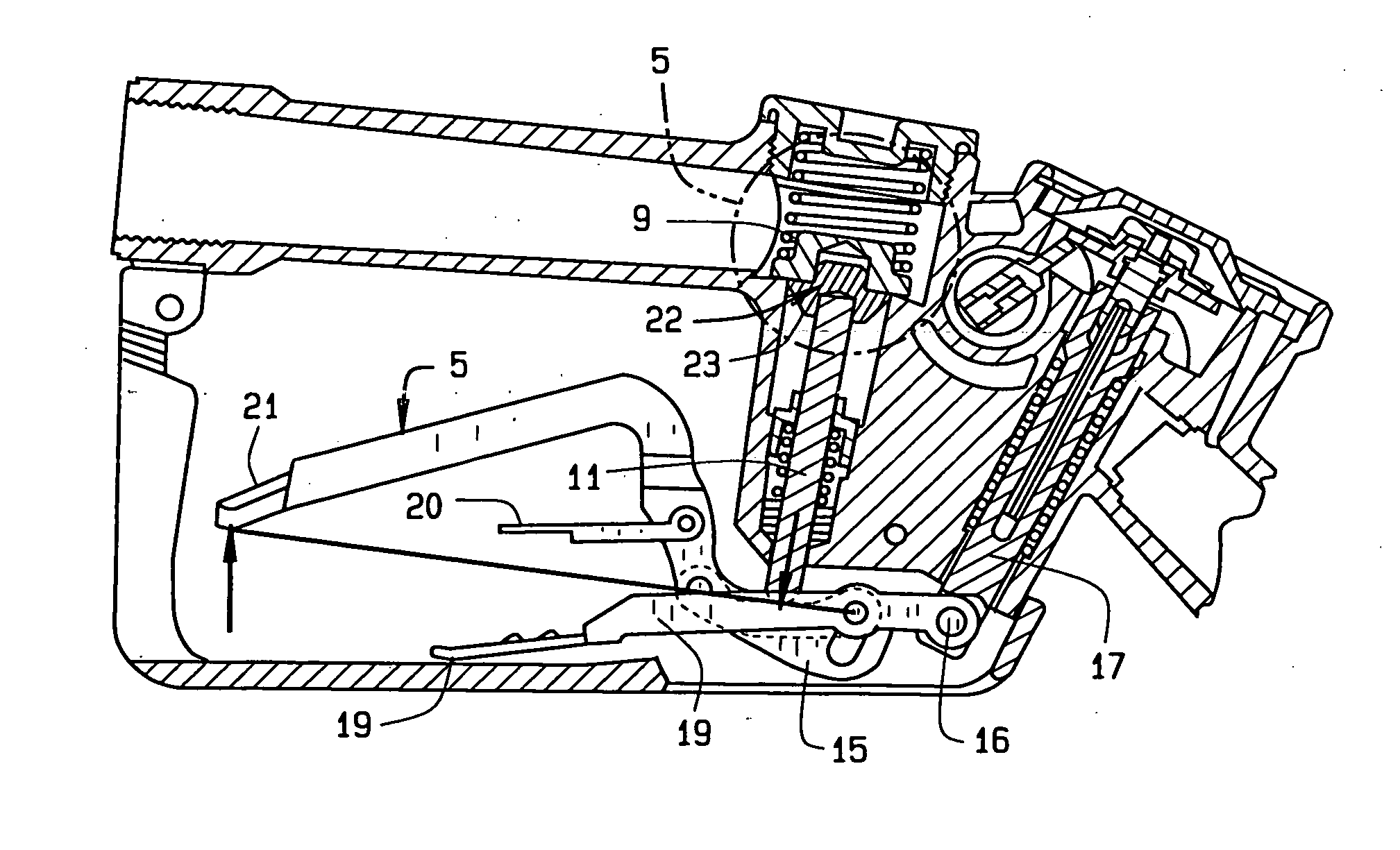
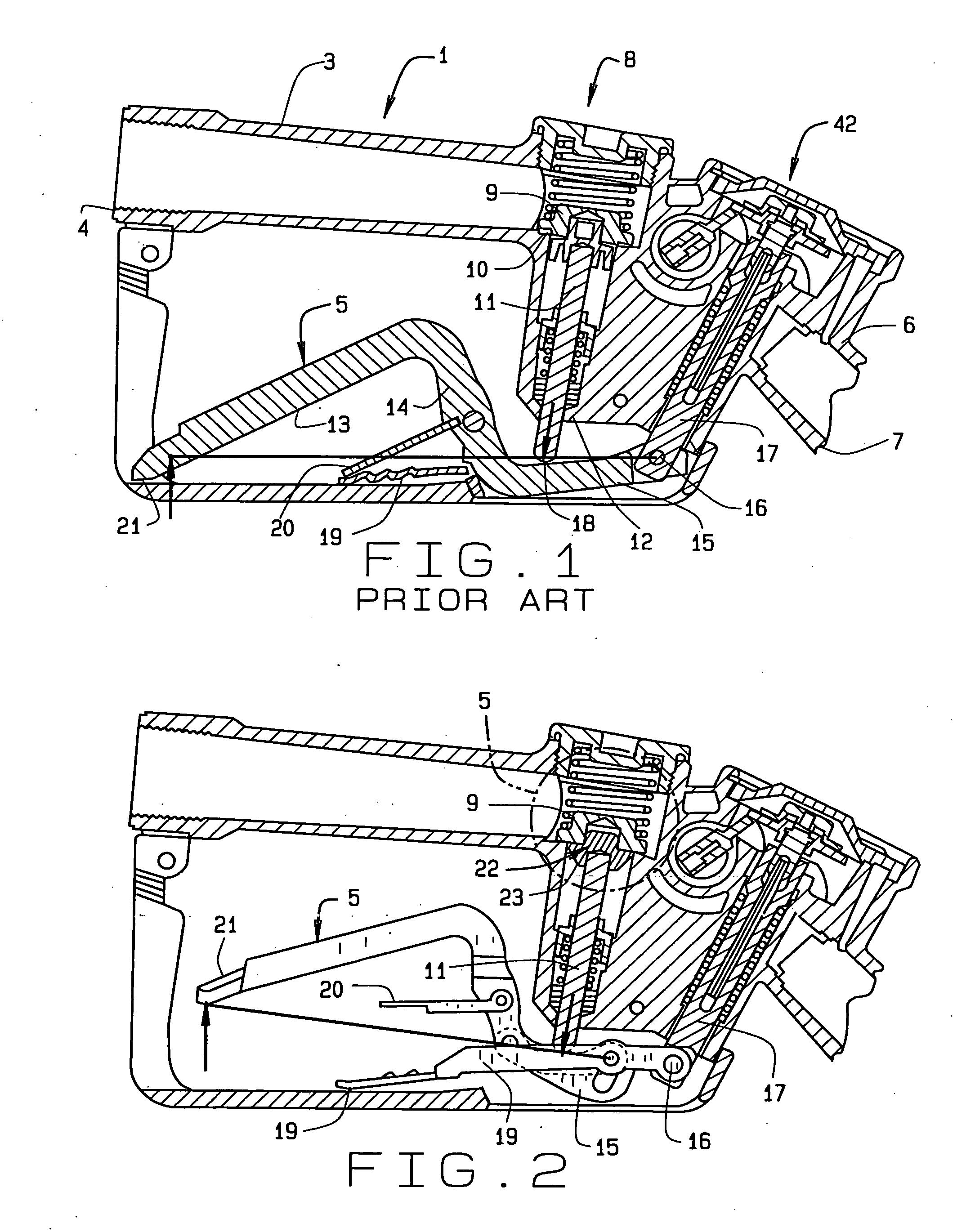
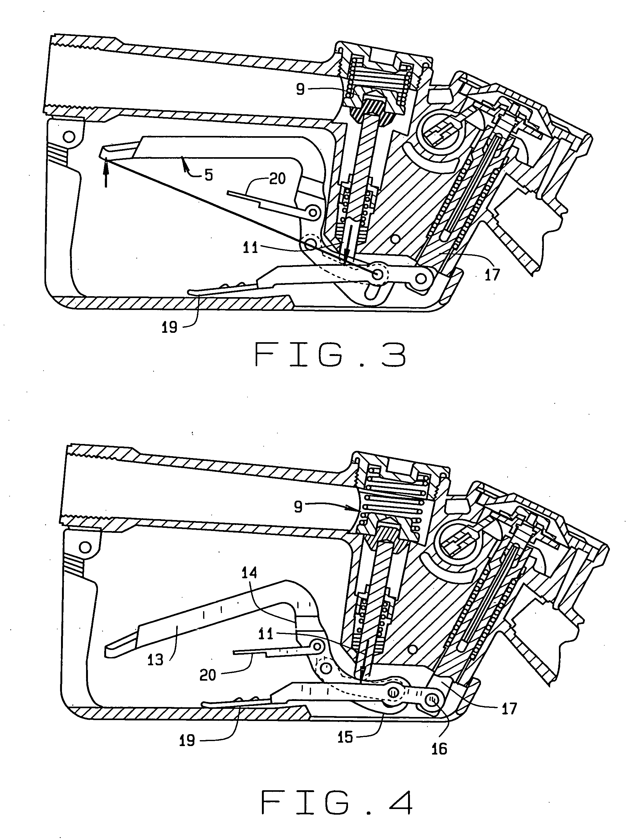
[0028]In referring to the drawings, and in particular FIG. 1, therein is shown a prior art style of nozzle construction 1, which as known, includes a housing 3 having an inlet 4 and an outlet 6 generally at the location of the formation and location of the spout 7 to the nozzle. The nozzle includes a main valve 8 that includes a poppet valve 9 that rests upon a valve seat 10, with the poppet valve having a poppet stem 11 that extends downwardly through the nozzle body, as at 12. Usually, the handle lever 5 includes a hand gripping portion 13 which is configured in a rather S shape, having an intermediate portion 14 and a forwardly extending integral portion 15 that secures by a pinned connection, as at 16, to the bottom of the automatic shutoff stem 17 for the shown nozzle. Thus, when the handle lever 5 is elevated, it pushes the poppet stem 11 upwardly, at the location of 18, to provide for an opening of the poppet valve and the flow of fuel through the nozzle, for dispensing into ...


PUM

PropertyMeasurementUnit
forceaaaaaaaaaa
diameteraaaaaaaaaa
angleaaaaaaaaaa

Abstract

A fuel dispensing nozzle, incorporating a uniquely shaped gasket for the poppet valve, generally of truncated shape, enhances the flow of fuel through the nozzle when actuated. A handle lever for the nozzle, which is designed having an elongated and enlarged end, includes elongated slots, that are pivotally pinned through both the latch plate, and the handle link, in order to reduce the space between the interconnection between the front of the latch plate to the bottom of the automatic shutoff stem, such that by lessening the distance between these components, thereby reducing the fulcrum point for the calculation of the force necessary to open the nozzle by raising its handle lever, and reduces the force necessary to achieve nozzle opening and actuation, to less than 5 lbs pressure during usage and application.

Description

CROSS REFERENCE TO RELATED APPLICATION[0001]This regular letters patent application claims priority to the provisional application having Ser. No. 61 / 996,431, filed on May 7, 2014.FIELD OF THE INVENTION[0002]The concept of this invention is to provide, generally, a nozzle, where its poppet valve is contoured into a truncated shape to enhance the flow of fuel through the nozzle as it is dispensing the same, and having a shift in the fulcrum point of the handle lever to lessen the force necessary to open the nozzle poppet valve for dispensing of fuel.BACKGROUND OF THE INVENTION[0003]A variety of nozzles have been designed over the years wherein their structure has been improved to add to the convenience of usage of the nozzles while dispensing fuel to a vehicle, or other fuel container, and while generally being applied to recover vapors, so as to minimize air pollution during fuel dispensing. With these types of nozzles, whether it is of the vacuum assist type, and more particularly ...

Claims


Application Information

Patent Timeline
Patent Type & Authority Applications(United States)
IPC IPC(8): B67D7/46B67D7/04
CPCB67D7/04B67D7/46B67D7/44B67D7/42
Inventor WEEPIE, KEITH J.
Owner HUSKY CORP
Why Eureka
Try Eureka