Heating assembly for a thermostatic valve and corresponding production method, and a thermostatic valve comprising such an assembly

Inactive Publication Date: 2015-11-12
VERNET SA
View PDF12 Cites 0 Cited by
  • Summary
  • Abstract
  • Description
  • Claims
  • Application Information

AI Technical Summary

Benefits of technology

[0030]The method according to the invention makes it pos

Problems solved by technology

However, this solution is delicate to manufacture, since during molding of the case, the plastic material injected so as to overmold the terminal part of the tube tends to pull, or even pull out, the electrical wires, unless sophisticated and therefore expensive injection molds are used, which furt

Method used


Image

  • Heating assembly for a thermostatic valve and corresponding production method, and a thermostatic valve comprising such an assembly
  • Heating assembly for a thermostatic valve and corresponding production method, and a thermostatic valve comprising such an assembly
  • Heating assembly for a thermostatic valve and corresponding production method, and a thermostatic valve comprising such an assembly

Examples


Embodiment Construction

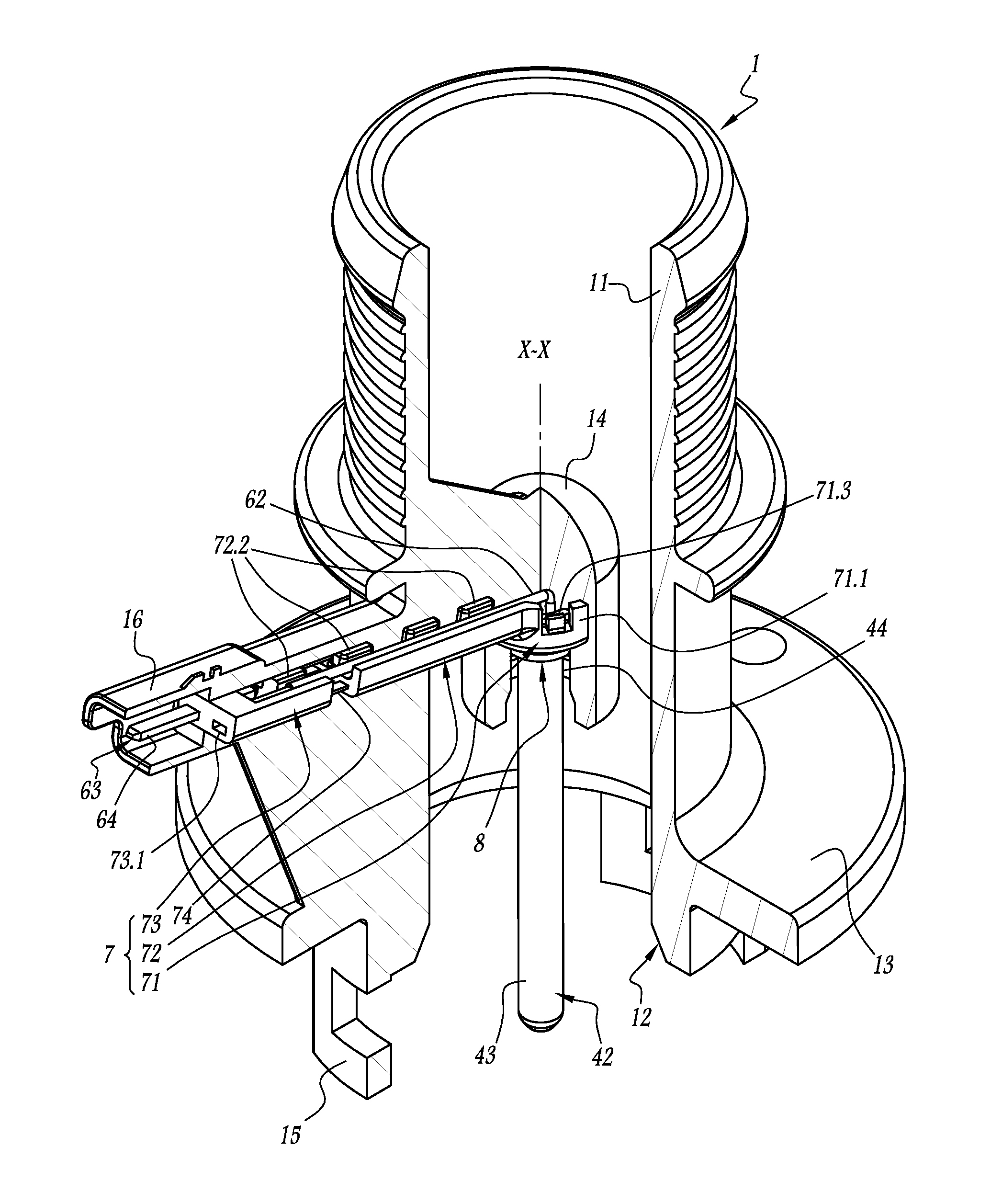
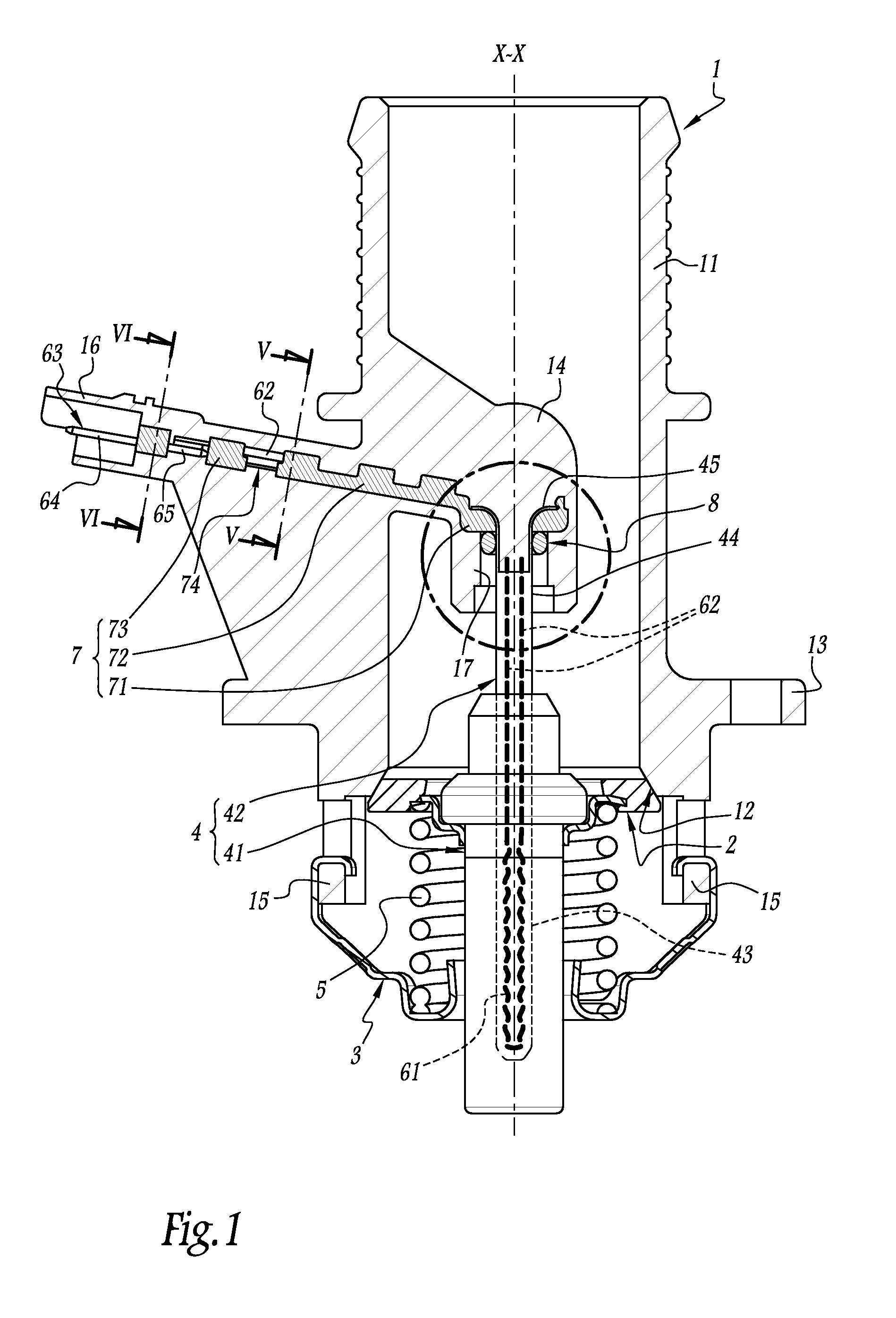
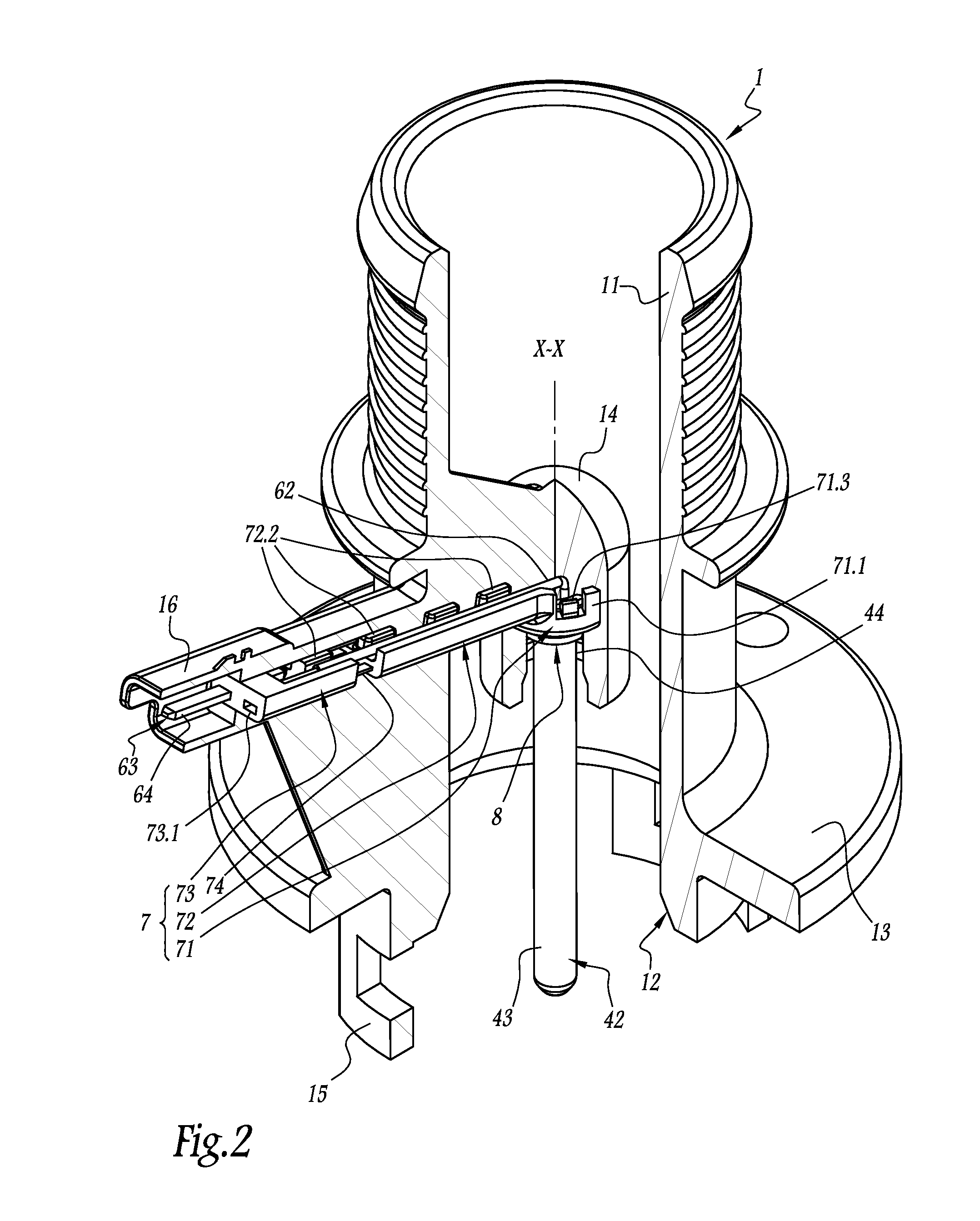
[0037]FIGS. 1 to 6 show a thermostatic valve comprising a housing 1 made from plastic, in which a fluid is designed to flow, in a manner regulated by the other components of the valve, in particular oil or a coolant liquid when the valve belongs to a cooling circuit for a heat engine.

[0038]The housing 1 comprises a tubular single-piece main body 11, here with a globally rectilinear shape centered around an axis X-X belonging to the cutting plane of FIG. 1. During use, the aforementioned fluid flows through the body 11, between its two longitudinal ends, while being regulated, here at one of said ends, by a closure disk 2 centered on the axis X-X and translatable along the axis: when this closure member is pressed tightly against a seat 12 delimited by the aforementioned end of the body 11, as shown in FIG. 1, the flow of the fluid is interrupted, whereas when the closure member 2 is separated from the seat 12, the fluid can flow freely around the closure member and thus enter or lea...


PUM


Abstract

This heating assembly comprises a thermally conductive tube (42), to be immersed in a thermally expandable material of a thermostatic element of a valve, an electric heating resistor disposed inside the tube and from which there extend electrically conductive wires (62), and a unitary housing (1) made from plastic, through which the fluid to be regulated flows via the valve, and which is secured by over-molding of a longitudinal end portion (44) of the tube. In order to make the molding of the over-molded housing simple and inexpensive to carry out, while being easy to adapt to various geometric forms of the heating assembly, the invention proposes that, before the housing is molded, a reinforcement (7) for supporting the wires outside the tube, which is separate from the housing, and to which the housing is secured by over-molding, can be securely mounted on the end portion of the tube and supports the wires outside the tube, said wires being externally mounted on the reinforcement, and, when the housing is being molded, keeps the wires in place while the plastic material of the housing coats these wires, the reinforcement and the end portion of the tube.

Description

FIELD OF THE INVENTION[0001]The present invention relates to a heating assembly for a thermostatic valve, as well as a method for manufacturing such a heating assembly. It also relates to a thermostatic valve comprising one such heating assembly.BACKGROUND OF THE INVENTION[0002]In many applications in the fluids field, in particular for cooling vehicle heat engines, thermostatic valves are used to distribute a fluid entering various circulation channels, based on the temperature of that fluid. These valves are said to be thermostatic because the movement of their inner closure member(s) is controlled by a thermostatic element, i.e., an element that comprises a cup containing a thermally expanding material and a piston able to slide relative to the cup under the action of the thermally expanding material when the latter expands.[0003]To distribute the fluid as a function of other parameters, in particular conditions outside the valve, such as the ambient temperature or the load of th...

Claims


Application Information

Patent Timeline
IPC IPC(8): F16K31/00H05B3/42H05B3/06
CPCF16K31/002Y10T137/6606H05B3/42H05B3/06H05B2203/014
Inventor POTTIE, NICOLASGAUTIER-GRAINDORGE, GUILLAUME
Owner VERNET SA
Why Eureka
Try Eureka