
Multicore fiber and method of manufacturing the same

Active Publication Date: 2015-11-12
THE FUJIKURA CABLE WORKS LTD
View PDF5 Cites 9 Cited by
  • Summary
  • Abstract
  • Description
  • Claims
  • Application Information

AI Technical Summary

Benefits of technology

The present invention provides a multicore fiber that allows for easy alignment of optical axes during use. The fiber has two external points of support, which helps to stabilize it and avoid rotational alignment issues. This makes it easier to align the optical axes of the fiber during use, and a manufacturing method is also provided to facilitate this process. Overall, the technical effect of the invention is to provide a more reliable and efficient multicore fiber for optical applications.

Problems solved by technology

However, in the manufacture method described above, such a tendency is observed that both ends of the flat external portion formed on a part of the external form of the multicore fiber preform is not a little rounded because of heat when the multicore fiber preform is drawn.
Therefore, there is concern that when this rounded external portion is placed on a predetermined mounting stage, the multicore fiber is unsteady on the mounting stage, and the alignment of optical axes becomes difficult.

Method used


Image

  • Multicore fiber and method of manufacturing the same
  • Multicore fiber and method of manufacturing the same
  • Multicore fiber and method of manufacturing the same

Examples


first embodiment

(1) First Embodiment

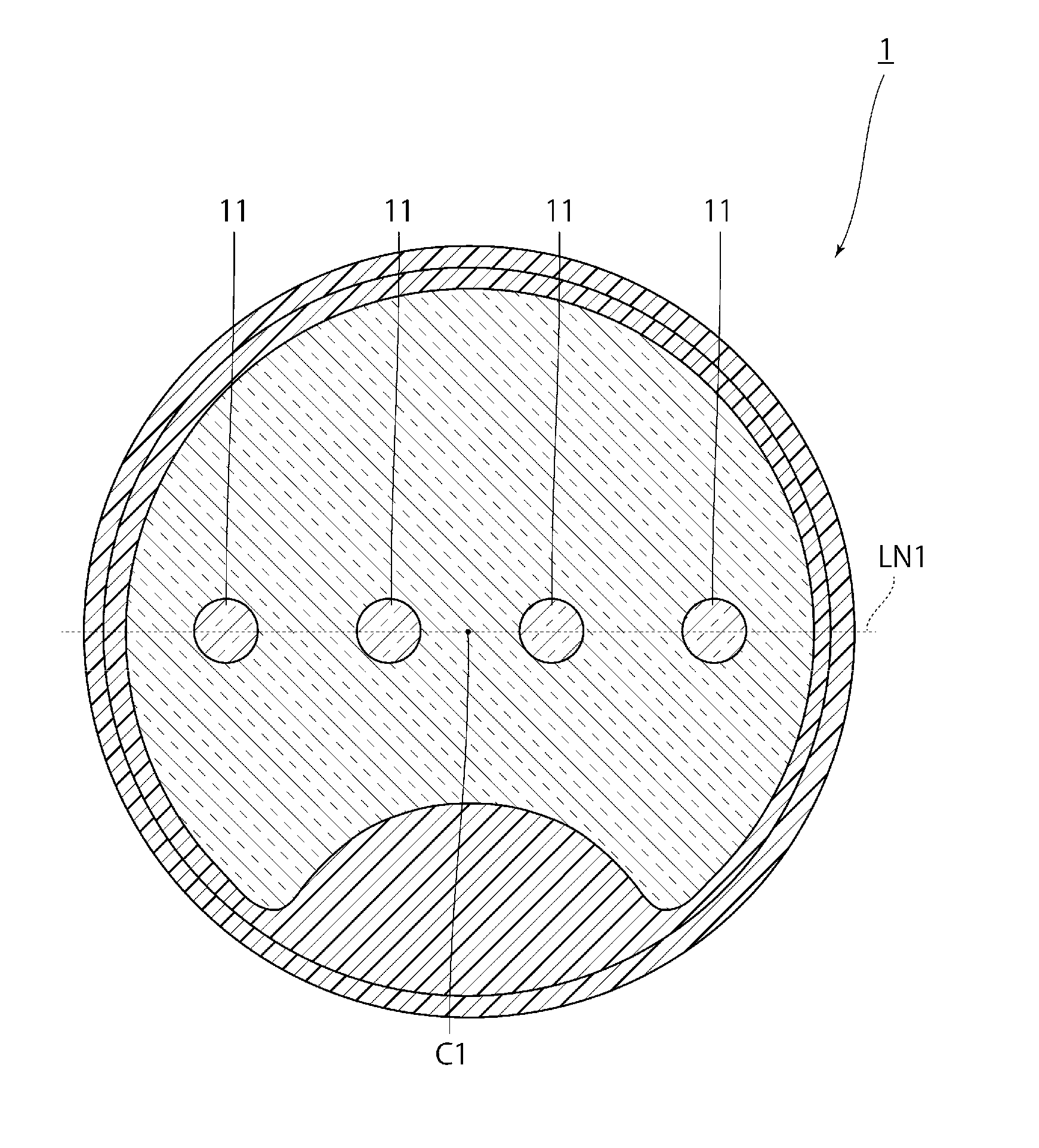
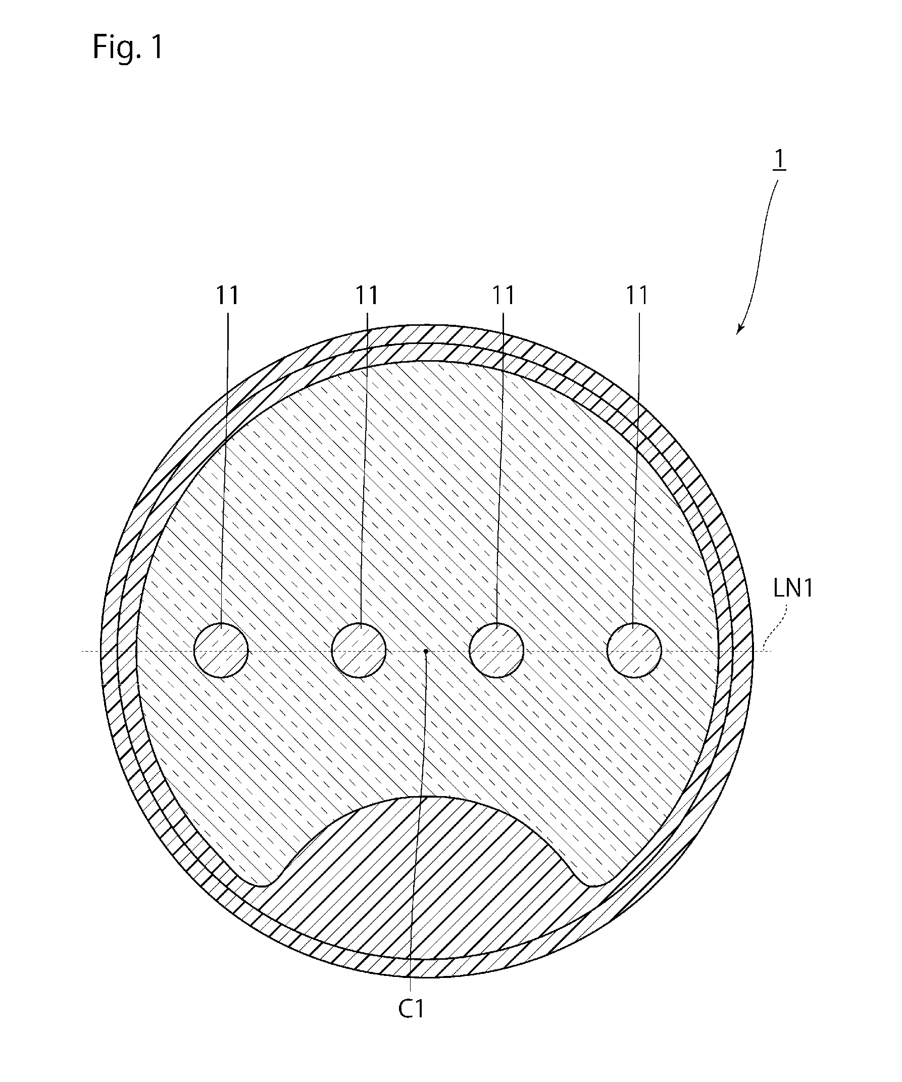
[0034]FIG. 1 is a diagram of a cross section perpendicular to the longer direction of a multicore fiber 1 according to an embodiment. As depicted in FIG. 1, a multicore fiber 1 according to the embodiment includes a plurality of cores 11, a cladding 12 that encloses the plurality of the cores 11, a first protective layer 13 that encloses the cladding 12, and a second protective layer 14 that encloses the first protective layer 13 as main components.

[0035]The plurality of the cores 11 is disposed as the cores 11 are arranged on a straight line LN1 passed through a center axis C1 of the cladding 12.

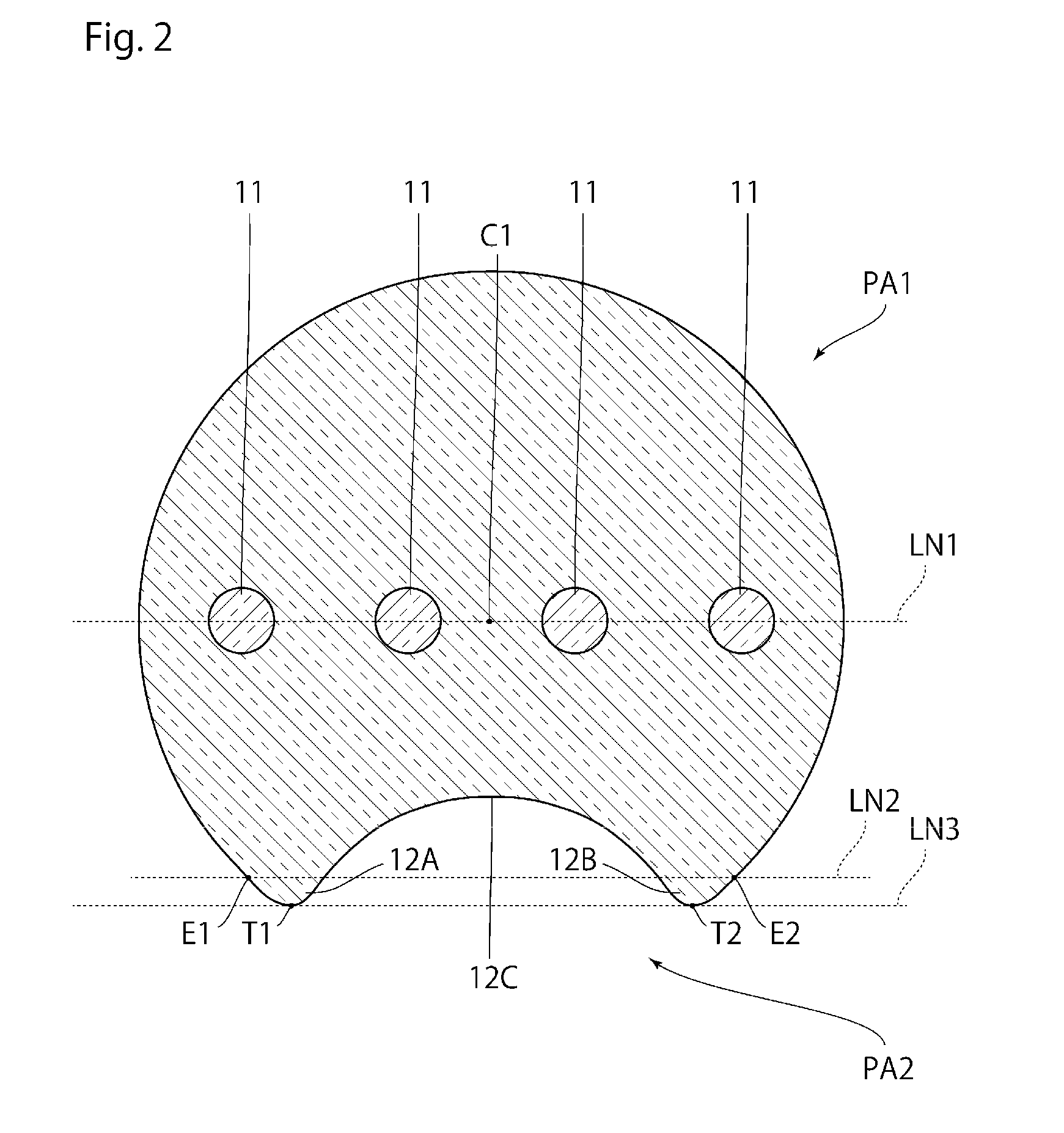
[0036]FIG. 2 is a diagram of the cores 11 and the cladding 12 observed from the same viewpoint in FIG. 1. As depicted in FIG. 2, the cladding 12 has an external form different from a cylindrical external form.

[0037]More specifically, the external form of the cladding 12 in the cross section is formed of an arc portion PA1 that is formed in an arc shape relative to the ce...

second embodiment

(2) Second Embodiment

[0070]Next, a second embodiment will be described in detail with reference to the drawings. However, in components of a multicore fiber according to the second embodiment, the components the same as or equivalent to the components according to the first embodiment are designated the same reference numerals and signs, and the overlapping description will be appropriately omitted.

[0071]FIG. 7 is a diagram of a cross section perpendicular to the longer direction of a multicore fiber 2 according to the second embodiment. As depicted in FIG. 7, the multicore fiber 2 according to the embodiment is different from the first embodiment only in that the structure of the non-arc portion PA2 is changed.

[0072]More specifically, in the first embodiment, a single recess 12C is formed between the pair of the projections 12A and 12B. On the other hand, in the embodiment, two recesses 12D and 12E are formed between a pair of projections 12A and 12B, and an intermediate projection...


PUM


Abstract

A multicore fiber according to an embodiment of the present invention includes a plurality of cores and a cladding that encloses the plurality of the cores. The external form of the cladding in a cross section is formed of an arc portion that is formed in an arc shape relative to the center axis of the cladding and a non-arc portion that is pinched between two ends of the arc portion and not formed in an arc shape relative to the center axis of the cladding. The non-arc portion is formed with a pair of projections projecting from two ends of the arc portion on the opposite side of the center axis relative to a straight line connecting the both ends of the arc portion and one or more of recesses pinched between the pair of the projections.

Description

BACKGROUND OF THE INVENTION[0001]The present invention relates to a multicore fiber and a method of manufacturing the multicore fiber, which are suitable for the case where an alignment of optical axes is facilitated.[0002]Presently, an optical fiber for use in optical fiber communication systems, which are generally popular, is in a structure in which one core is enclosed with a cladding, in which an optical signal is propagated through the inside of the core and information is transmitted.[0003]In the optical fiber communication system in these years, a large number of from a few tens to a few hundreds of optical fibers are used, and the amount of information for transmission is dramatically increased. In order to decrease the number of optical fibers in such an optical fiber communication system, a multicore fiber is proposed in which a plurality of cores is enclosed with a cladding.[0004]For example, in a multicore fiber described in Patent Document 1 below, 16 cores are enclose...

Claims


Application Information

Patent Timeline
IPC IPC(8): G02B6/02
CPCG02B6/02042C03B37/01222C03B37/01225C03B37/01231C03B37/027C03B2203/02C03B2203/10C03B2203/34
Inventor ISHIDA, ITARUMATSUO, SHOICHIRO
Owner THE FUJIKURA CABLE WORKS LTD
Learn More