Optical bench subassembly having integrated photonic device

Inactive Publication Date: 2016-09-22
SENKO ADVANCED COMPONENTS
View PDF4 Cites 17 Cited by
  • Summary
  • Abstract
  • Description
  • Claims
  • Application Information

AI Technical Summary

Benefits of technology

[0024]The present invention provides an improved structure to facilitate optical alignment of photonic device to an optical bench, which overcomes the drawbacks of the prior art. The present invention combines

Problems solved by technology

This is challenging especially for multiple fiber applications, where multiple optical fibers need to be optically aligned to multiple optoelectronic devices using an active optical alignment approach in which the position and orientation of the optical fiber(s) is adjusted by machinery until the amount of light transferred between the fiber and optoelectronic is maximized.
Active optical alignment involves relatively complex, low throughput processes since the VCSEL or PD must be energized during the active alignment process.
Manufacturers of integrated circuits often have expensive capital equipment capable of sub-micron alignment (e.g. wafer probers and handlers for testing integrated circuits), whereas companies that package chips generally have less capable machinery (typically several micron alignment tolerances which is not adequate for single-mode devices) and often use manual operations.
The current state of the art is expensive due to the inclusion of a package, excludes the use of common electronics and assembly processes, and/or often not suited to single-mode applications.
The package is a relatively more expensive assembly (which includes expensive circuit components, such as ICs, etc.) as compared to the hermetic f

Method used


Image

  • Optical bench subassembly having integrated photonic device
  • Optical bench subassembly having integrated photonic device
  • Optical bench subassembly having integrated photonic device

Examples


Embodiment Construction

[0040]This invention is described below in reference to various embodiments with reference to the figures. While this invention is described in terms of the best mode for achieving this invention's objectives, it will be appreciated by those skilled in the art that variations may be accomplished in view of these teachings without deviating from the spirit or scope of the invention.

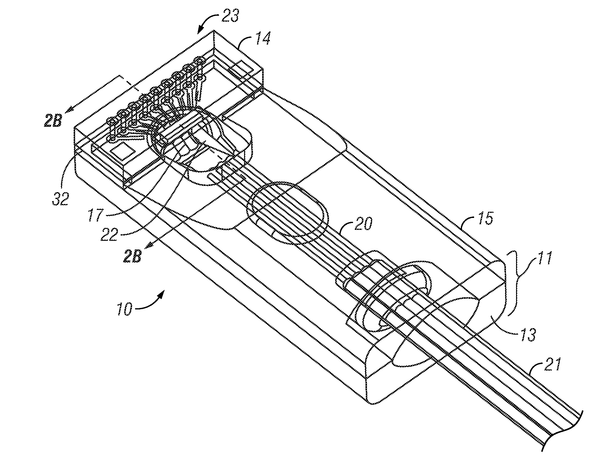
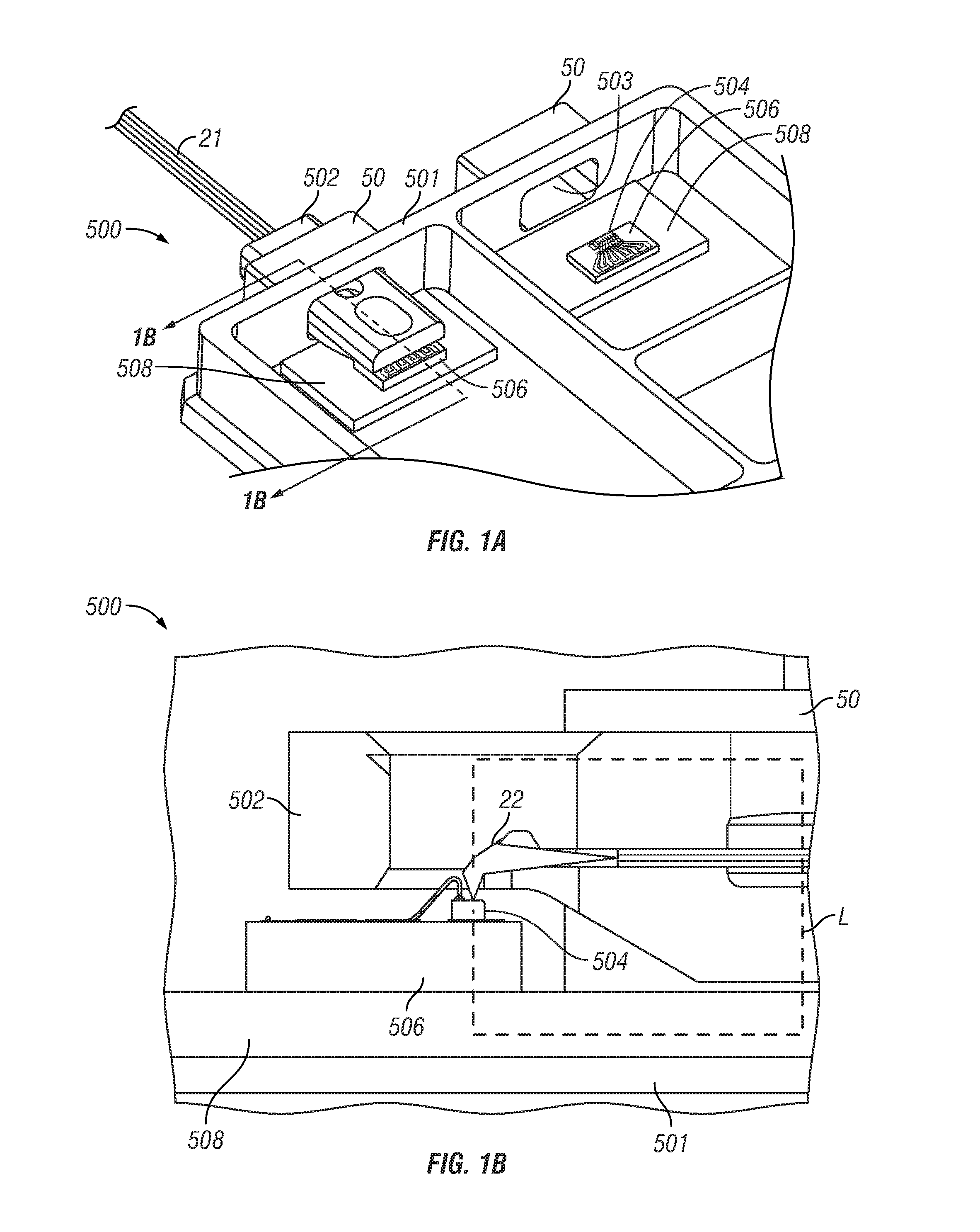
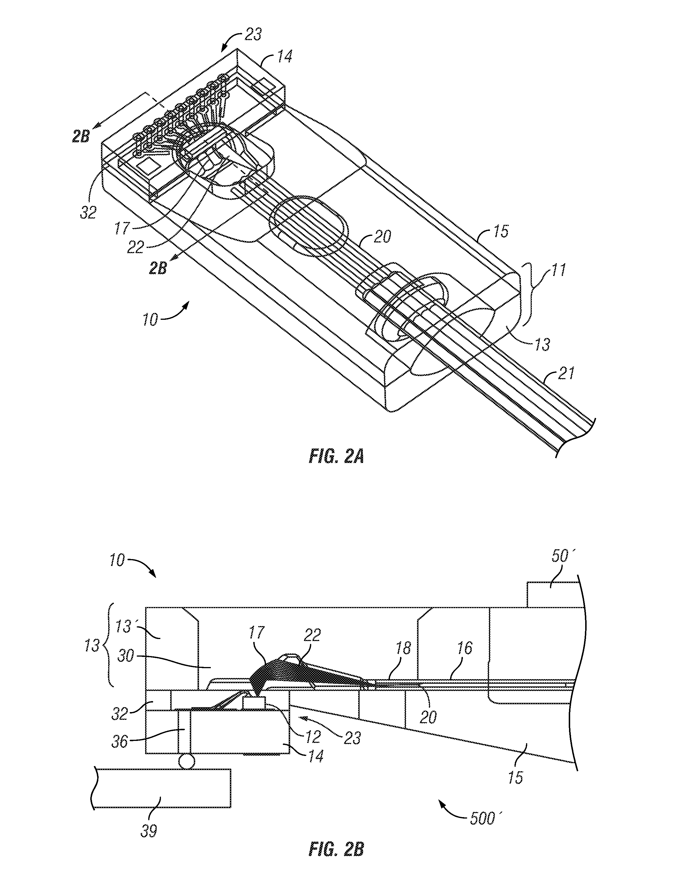
[0041]The present invention provides an improved structure to facilitate optical alignment of photonic device to an optical bench, which overcomes the drawbacks of the prior art. The present invention combines a photonic device with an optical bench in a subassembly, so that alignment of the optical coupling of the photonic device with the optical bench can be performed outside of the optoelectronic package assembly.

[0042]In accordance with the present invention, the photonic device is attached to a base of the optical bench, with its optical input / output in optical alignment with the optical output / input ...


PUM

PropertyMeasurementUnit
Optical propertiesaaaaaaaaaa

Abstract

An optical bench subassembly including an integrated photonic device. Optical alignment of the photonic device with the optical bench can be performed outside of an optoelectronic package assembly before attaching thereto. The photonic device is attached to a base of the optical bench, with its optical input/output in optical alignment with the optical output/input of the optical bench. The optical bench supports an array of optical fibers in precise relationship to a structured reflective surface. The photonic device is mounted on a submount to be attached to the optical bench. The photonic device may be actively or passively aligned with the optical bench. After achieving optical alignment, the submount of the photonic device is fixedly attached to the base of the optical bench. The optical bench subassembly may be structured to be hermetically sealed as a hermetic feedthrough, to be hermetically attached to a hermetic optoelectronic package.

Description

PRIORITY CLAIM[0001]This application:[0002](1) claims the priority of U.S. Provisional Patent Application No. 62 / 136,601 filed on Mar. 22, 2015;[0003](2) is a continuation-in-part of U.S. patent application Ser. No. 13 / 861,273 filed on Apr. 11, 2013, which:[0004](a) claims the priority of U.S. Provisional Patent Application No. 61 / 623,027 filed on Apr. 11, 2012,[0005](b) claims the priority of U.S. Provisional Patent Application No. 61 / 699,125 filed on Sep. 10, 2012, and[0006](c) is a continuation-in-part of U.S. patent application Ser. No. 13 / 786,448 filed on Mar. 5, 2013, which claims the priority of U.S. Provisional Patent Application No. 61 / 606,885 filed on Mar. 5, 2012;[0007](3) is a continuation-in-part of U.S. patent application Ser. No. 14 / 714,211 filed on May 15, 2015, which[0008](a) claims the priority of U.S. Provisional Patent Application No. 61 / 994,094 filed on May 15, 2014, and[0009](b) is a continuation-in-part of U.S. patent application Ser. No. 14 / 695,008 filed on A...

Claims


Application Information

Patent Timeline
IPC IPC(8): G02B6/42
CPCG02B6/4248G02B6/4214G02B6/423G02B6/4245G02B6/4257G02B6/425G02B6/3652G02B6/3833G02B6/3839G02B6/4246G02B6/4249G02B6/4292Y10T29/49
Inventor VALLANCE, ROBERT RYANLI, SHUHE
Owner SENKO ADVANCED COMPONENTS
Why Eureka
Try Eureka