Demountable connection of an optical connector and an optical bench based connector using an alignment coupler

Active Publication Date: 2020-04-23
SENKO ADVANCED COMPONENTS
View PDF8 Cites 2 Cited by
  • Summary
  • Abstract
  • Description
  • Claims
  • Application Information

AI Technical Summary

Benefits of technology

The present invention provides a solution for connecting optical benches and optical connectors by providing a demountable and reconnectable connection. This is achieved through the use of an optical coupler with an opening that can accommodate the optical bench. The coupler has a passive alignment structure that allows for easy adjustment of the optical bench to achieve the desired alignment. The optical bench is fixed in position relative to the coupler using epoxy, soldering, or welding. The invention provides a more efficient and flexible way to connect optical benches and connectors, making it easier to align and disconnect them.

Problems solved by technology

Second, they are not dimensionally stable and can change size and shape especially when subjected to elevated temperatures such as those found in computing and networking hardware.
Therefore, temperature cycles cause misalignment between the optical fibers and the optical elements on the PIC devices.
In some cases, the polymers cannot withstand the processing temperatures used while soldering PIC devices onto printed circuit boards.
In other words, optical fiber is not removably attachable to the PIC device, and the fiber connection, and separation would be destructive and not reversible (i.e., not reconnectable).

Method used


Image

  • Demountable connection of an optical connector and an optical bench based connector using an alignment coupler
  • Demountable connection of an optical connector and an optical bench based connector using an alignment coupler
  • Demountable connection of an optical connector and an optical bench based connector using an alignment coupler

Examples


Embodiment Construction

[0025]This invention is described below in reference to various embodiments with reference to the figures. While this invention is described in terms of the best mode for achieving this invention's objectives, it will be appreciated by those skilled in the art that variations may be accomplished in view of these teachings without deviating from the spirit or scope of the invention.

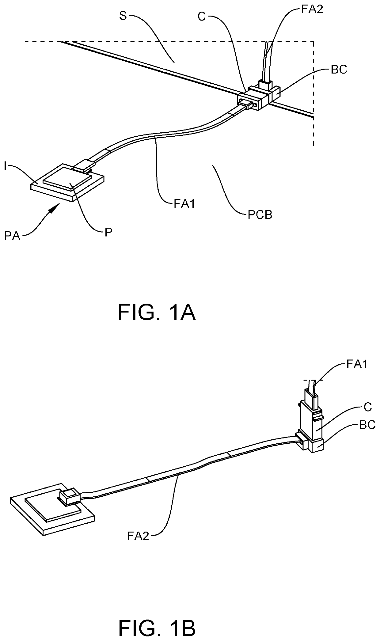
[0026]The present invention overcomes the drawbacks of the prior art by providing a demountable / separable and reconnectable connection between an optical connector C and an optical bench OB using an alignment coupler A to facilitate active alignment of the optical bench OB to the optical connector C.

[0027]Referring to FIGS. 1A and 1B, the optical bench and the coupler together form an optical bench based connector BC. In FIG. 1A, the connector C may be at a termination of an optical fiber array FA1 having another termination at another end coupled to a photonic apparatus PA (e.g., a photonic integrated cir...


PUM


Abstract

An alignment coupler is provided to facilitate active alignment of the optical bench to the optical connector. The optical bench and the coupler together form an optical bench based connector. A method of demountable connection of an optical connector to an optical bench based connector, comprising: providing a coupler, wherein the coupler has an opening sized to receive an optical bench with clearance for relative movement between the optical bench and the coupler to facilitate alignment, and wherein the coupler is provided with a passive alignment structure structured to demountably couple to the connector; demountably coupling the coupler to the connector; placing the optical bench in the opening of the coupler; actively aligning the optical path between the optical bench and the connector to reach a desired optical alignment between the optical bench and the connector, by adjusting a position of the optical bench within the clearance of the opening of the coupler; fixing the position of the optical bench relative to the coupler at the desired optical alignment, whereby the optical bench is optically aligned to the connector using the coupler, thereby allowing subsequent demountable coupling of the optical bench to the connector by demountable coupling of the coupler.

Description

PRIORITY CLAIM[0001]This application claims the priorities of (a) U.S. Provisional Patent Application No. 62 / 749,616 filed on Oct. 23, 2018; and (b) U.S. Provisional Patent Application No. 62 / 749,618 filed on Oct. 23, 2018. These applications are fully incorporated by reference as if fully set forth herein. All publications noted below are fully incorporated by reference as if fully set forth herein.BACKGROUND OF THE INVENTION1. Field of the Invention[0002]The present invention relates to a demountable optical connection, and more particularly to the optical connection of an optical connector to an optical bench based connector, and further in connection with optical connection for photonic circuit boards.2. Description of Related Art[0003]Photonic integrated circuits (PICs) or integrated optical circuits are part of an emerging technology that uses light as a basis of operation as opposed to an electric current. A PIC device integrates multiple (at least two) photonic functions and...

Claims


Application Information

Patent Timeline
IPC IPC(8): G02B6/38
CPCG02B6/3897G02B6/3882G02B6/3839G02B6/30G02B6/3652G02B6/3885G02B6/4214G02B6/422G02B6/4292G02B6/26
Inventor CHEN, YANGVALLANCE, ROBERT RYAN
Owner SENKO ADVANCED COMPONENTS
Why Eureka
Try Eureka