Optical fiber connector, method for manufacturing optical fiber connector, method for connecting optical fiber connector and optical fiber, and assembled body of optical fiber connector and optical fiber

Inactive Publication Date: 2015-05-21
HITACHI CHEM CO LTD
View PDF7 Cites 12 Cited by
  • Summary
  • Abstract
  • Description
  • Claims
  • Application Information

AI Technical Summary

Benefits of technology

[0019]An optical fiber connector of the present invention facilitates alignment of an optical fiber and an optical

Problems solved by technology

Such an optical fiber connector, however, requires an optical fiber mounting groove be formed by cutting work by means of dicing and therefore work efficiency is poor.
Hence, the optical fiber is misaligned in some cases.
Further, an optical fiber undergoes more significant misalignment in this method unless the optical waveguide is formed on a hard substrate with good dimensional st

Method used


Image

  • Optical fiber connector, method for manufacturing optical fiber connector, method for connecting optical fiber connector and optical fiber, and assembled body of optical fiber connector and optical fiber
  • Optical fiber connector, method for manufacturing optical fiber connector, method for connecting optical fiber connector and optical fiber, and assembled body of optical fiber connector and optical fiber
  • Optical fiber connector, method for manufacturing optical fiber connector, method for connecting optical fiber connector and optical fiber, and assembled body of optical fiber connector and optical fiber

Examples


first embodiment

Modification of First Embodiment

[0161]More than one lower clad layer and upper clad layer may be formed to obtain a desired thickness.

[0162]In the optical fiber connector 1 described above, the optical path changing mirror 31 is an optical path changing mirror provided with the metal film. However, an optical path changing mirror using a difference of refractive indices between an air layer and the core layer is also available.

[0163]Also, the V-shaped groove 30 and the optical path changing mirror 31 may be omitted.

[0164]Particularly, in a case where the substrate main body 11 has adhesiveness, the adhesive layer 13 of the substrate 10 may be omitted. The adhesive layer 13 may form part of the lower clad layer as the second lower clad layer.

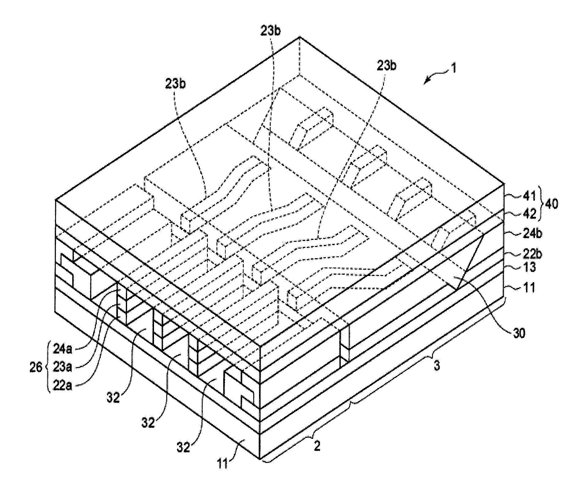
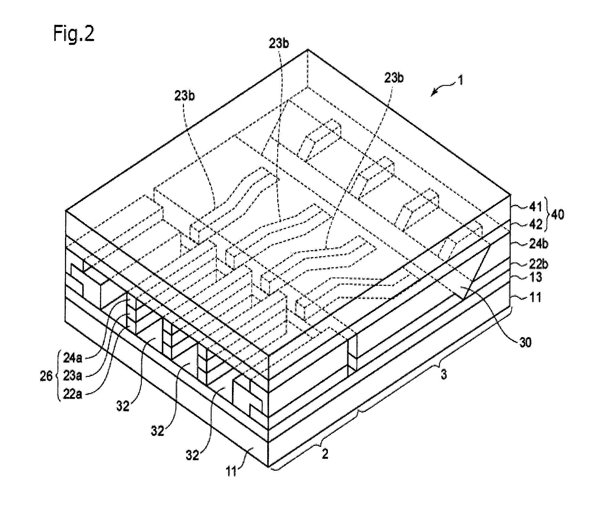
[0165]In the optical fiber connector 1 described above, the fiber guide side first lower clad layer 22a is present on the substrate 10, on top of which the fiber guide core pattern 23a is present, and on top of which the fiber guide side upper cl...

second embodiment

Structure of Optical Fiber Connector

[0166]An optical fiber connector of a second embodiment is the optical fiber connector of the first embodiment above having an adhesive introduction slit that allows an outside of the optical fiber guide member 2 and the fiber guide grooves 32 to communicate instead of the slit groove 25 or in addition to the slit groove 25.

[0167]In the optical fiber connector of the second embodiment, the fiber guide groove 32 communicates with the outside via an optical fiber insertion opening of the fiber guide groove 32 and also communicates with the outside via the adhesive introduction slit. Hence, when the adhesive is introduced from one of the optical fiber insertion opening and the adhesive introduction slit, air inside the fiber guide groove 32 flows out from the other one of the optical fiber insertion opening and the adhesive introduction slit. The adhesive can be therefore readily introduced into the fiber guide groove 32. When the optical fiber is fi...

example 1

Manufacturing of Optical Fiber Connector 1A

First Step

[0229]The 20-μm-thick lower clad layer forming resin film obtained as above was cut into a size of 100×100 μm and the protection film was peeled off. The resulting film was laminated on the second lower clad layer surface side using a vacuum laminator under the same conditions as above. Subsequently, 250 mJ / cm2 of an ultraviolet ray (wavelength of 365 nm) was irradiated to the resulting film using an UV exposure device (EXM-1172 available from ORC Manufacturing Co., Ltd.) from the carrier film side via a negative photomask having four unexposed portions, each measuring 95 μm×3.0 mm. Thereafter, the carrier film was peeled off and the first lower clad layer was etched away using a developer (1% aqueous solution of potassium carbonate). Subsequently, the resulting film was rinsed with water and dried and cured by heating at 170° C. for one hour. Openings, each measuring 95 μm×3.0 mm, were thus formed in a portion in which the fiber ...


PUM

PropertyMeasurementUnit
Lengthaaaaaaaaaa
Lengthaaaaaaaaaa
Diameteraaaaaaaaaa

Abstract

An optical fiber connector in which: an optical fiber guide member includes a fiber guide side substrate portion forming part of a substrate, a fiber guide pattern, and a lid member; and an optical waveguide includes an optical waveguide side substrate portion adjacent to the fiber guide side substrate portion, an optical waveguide side first lower clad layer, an optical signal transmission core pattern, and an optical waveguide side upper clad layer. The fiber guide pattern is formed of a plurality of guide members aligned parallel to one another at intervals. A space defined by every two adjacent guide members, the fiber guide side substrate portion, and a fiber guide side lid member portion forms a fiber guide groove. The fiber guide groove is present on an extension of the optical signal transmission core pattern in an optical path direction. The optical fiber connector facilitates alignment of an optical fiber and an optical waveguide core and also facilitates mounting of the optical fiber with hardly any misalignment of the optical fiber.

Description

TECHNICAL FIELD[0001]The present invention relates to an optical fiber connector, a method for manufacturing an optical fiber connector, a method for connecting an optical fiber connector and an optical fiber, and an assembled body of an optical fiber connector and an optical fiber, and more particularly, to an optical fiber connector that facilitates alignment of an optical fiber and an optical waveguide core independently of a substrate with hardly any misalignment of the optical fiber, a method for manufacturing an optical fiber connector, a method for connecting an optical fiber connector and an optical fiber, and an assembled body of an optical fiber connector and an optical fiber.BACKGROUND ART[0002]Generally, an optical cable (also called an optical fiber cable) is used extensively for home and industrial information communications due to its capability of allowing high-speed, large-volume information communications. Also, for example, an automobile is equipped with various e...

Claims


Application Information

Patent Timeline
IPC IPC(8): G02B6/38G02B6/255G02B6/26
CPCG02B6/3807G02B6/255G02B6/26G02B6/136G02B6/138G02B6/30G02B6/12002G02B6/4214G02B6/3692G02B6/3652G02B6/4249
Inventor SAKAI, DAICHIKURODA, TOSHIHIROMINAKAWA, KAZUSHIAOKI, HIROMICHIBETSUI, HIROSHISEGAWA, KOUTAUCHIGASAKI, MASAOYAGI, SHIGEYUKISHIBATA, TOMOAKI
Owner HITACHI CHEM CO LTD
Why Eureka
Try Eureka