Linking damper system for a rotorcraft landing gear

a damper system and landing gear technology, applied in the field of linking systems, can solve the problems of unstable coupling of each blade about the lead-lag axis, unbalance, and non-uniform distribution of blades, so as to reduce interference, reduce interference, and reduce the effect of friction

Active Publication Date: 2015-11-19
AIRBUS HELICOPTERS DEUT GMBH
View PDF4 Cites 4 Cited by
  • Summary
  • Abstract
  • Description
  • Claims
  • Application Information

AI Technical Summary

Benefits of technology

[0020]The present invention aims at providing a damping device capable of mitigating the effects a hypothetical ground resonance phenomenon while limiting the interference with the design of the rotorcraft, that is, without the need for additional attachment points to the fuselage. Moreover, the present invention looks to provide efficient damping in any selected direction.

Problems solved by technology

The oscillations of each blade about its lead-lag axis can become coupled in unstable manner with movements of the fuselage of the rotorcraft that depend on the elastic deformation modes of the landing gear.
As they rotate, the blades move away from their equilibrium positions and can thus become distributed non-uniformly.
This non-uniform distribution of the blades gives rise to unbalance, since the center of gravity of the rotor moves away from the axis of rotation of the rotor.
In the case the damper device is associated to the landing gear structure, the adaptation of the landing gear is normally complex.
Besides, the incorporation of damping parts is often prejudicial for the aerodynamic efficiency, the weight of the rotorcraft and the compactness of the structure.
The design of a skid landing gear is, in consequence, a generally lengthy and difficult process.
Other prior art documents disclose vibration absorbers for the main excitation frequencies of a helicopter—they are thus not specifically designed for dealing with the instability derived from the ground resonance.

Method used


Image

  • Linking damper system for a rotorcraft landing gear
  • Linking damper system for a rotorcraft landing gear
  • Linking damper system for a rotorcraft landing gear

Examples


Embodiment Construction

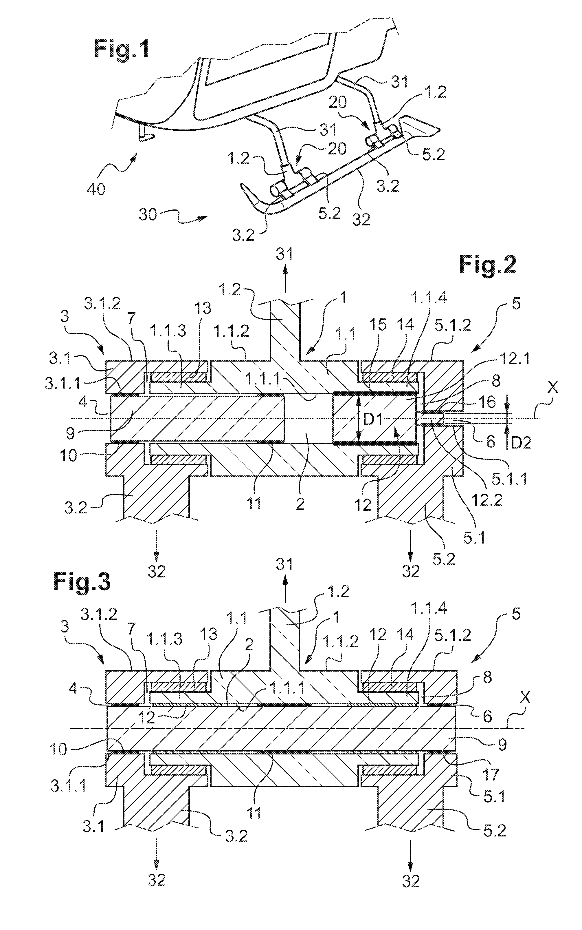
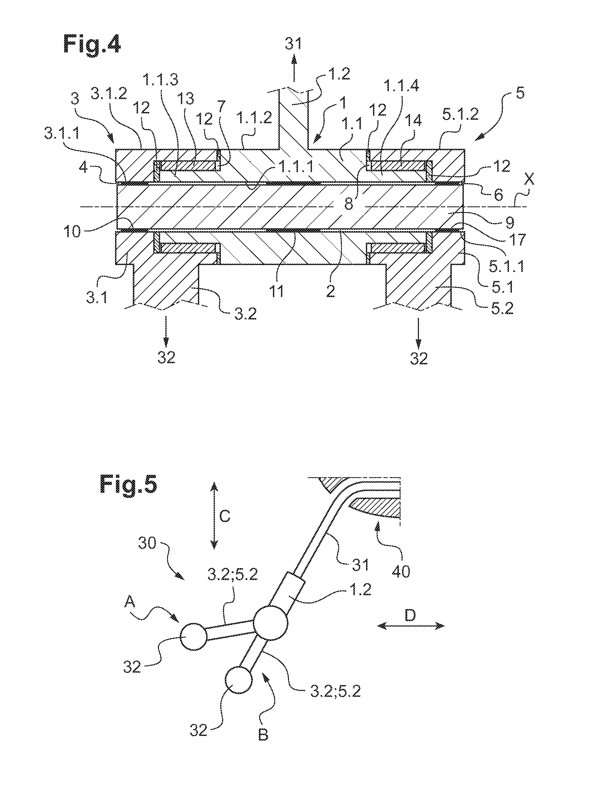
[0088]FIG. 1 represents a rotorcraft 40 having a skid landing gear 30, each of the two skids 32 of the landing gear 30 extending parallel to the longitudinal direction of the rotorcraft 40 and being attached to the cross tubes 31 by inventive linking systems 20. The cross tubes 31 are in turn attached to the fuselage of the rotorcraft 40.

[0089]In this embodiment, each one of the two skids 32 is linked to two cross tubes 31 via two linking systems 20, and each linking system 20 has one attachment to the cross tube 31 via the cross tube attaching means 1.2 and two attachment to the skid 32 via the first 3.2 and second 5.2 lateral attaching means.

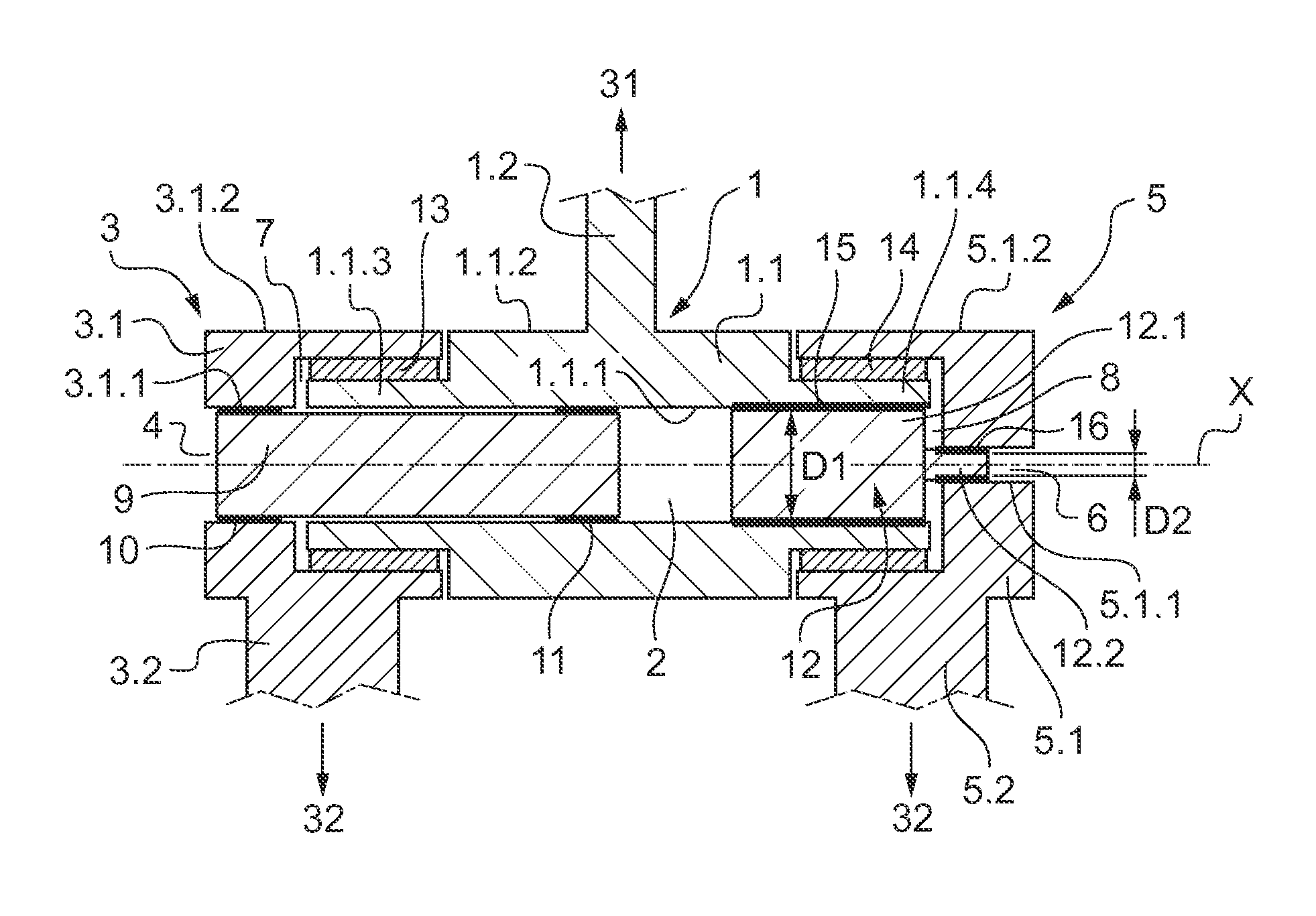
[0090]FIG. 2 depicts a longitudinal section of a linking system 20 having the torsion bar spring 9 located in the main cylindrical cavity 2, 4, 6, rigidly attached by first lateral 10 and central 11 annular connecting elements to the first lateral annular hollow part 3 and to the cross tube-sided part 1. The rotary damper element 12 is linked ...


PUM


Abstract

A linking system for attaching a cross tube to a skid of a landing gear of a rotorcraft, the linking system comprising a hinge element, means for connecting the hinge element to the cross tube and means for connecting the hinge element to the skid, the hinge element in turn comprising a cross tube-sided part and a skid-sided part able to rotate with respect to one another, a torsion bar spring and a rotary damper element suitable for dissipating a ground resonance excitation energy when the rotation of the cross tube-sided part with respect to the skid-sided part occurs.

Description

CROSS REFERENCE TO RELATED APPLICATION[0001]This application claims priority to European patent application No. EP 14 400036.1 filed on May 13, 2014, the disclosure of which is incorporated in its entirety by reference herein.BACKGROUND OF THE INVENTION[0002](1) Field of the Invention[0003]The present invention relates to a linking system for attaching a cross tube and a skid of a landing gear, the linking system having a hinge arrangement and being suitable for the dissipation of oscillations derived from the ground resonance phenomenon.[0004](2) Description of Related Art[0005]Conventionally, a rotorcraft has a landing gear on which the aircraft stands when on the ground. More particularly, skid landing gears are provided with two skids extending parallel to the longitudinal direction of the rotorcraft. The skids are for coming into contact with the ground and they are arranged on either side of the fuselage of the rotorcraft.[0006]Furthermore, skid landing gears are usually provi...

Claims


Application Information

Patent Timeline
Patent Type & Authority Applications(United States)
IPC IPC(8): B64C25/62
CPCB64C25/62B64C25/52B64C2025/325
Inventor OBERINGER, OLIVER
Owner AIRBUS HELICOPTERS DEUT GMBH
Why Eureka
Try Eureka