Container lid and valve

a container lid and valve technology, applied in the direction of lids, resealable lids/covers, packaging, etc., can solve the problems of type lids, complex mechanical mechanisms of resealable container lids, and not resealable after, so as to facilitate sealing engagement and suitability. flexibility

Active Publication Date: 2015-11-19
LIQUISTOP
View PDF11 Cites 7 Cited by
  • Summary
  • Abstract
  • Description
  • Claims
  • Application Information

AI Technical Summary

Benefits of technology

[0005]The valve may include a generally elliptical configuration that has side portions at opposite ends of a major axis defined through the valve and top and bottom portions at opposite ends of a minor axis defined through the valve. The side portions of the valve may be configured to flex as a result of depressing one or both of the pair of protuberances to enable the pair of protuberances to be spring loaded and to form a fluid tight seal with surfaces of the body member when the pair of protuberances are positioned within the pair of apertures. The top portion of the valve may be thinner and / or thicker than the bottom portion to provide the valve with a suitable flexibility. In embodiments, the top portion of the valve may be spaced apart from the interior surface of the body member to facilitate a sealed engagement between the pair of protuberances and the apertures when the valve is coupled to the interior surface of the body member. In certain embodiments, the top portion of the valve may be configured to rest on the interior surface of the body member.
[0007]Each of the apertures may be provided in a corresponding recess provided on the body member of each lid. In embodiments, the corresponding recesses and / or apertures are positioned on the body member in a diametrically opposite relationship relative to one another. The corresponding recesses may be configured to receive a corresponding one of the pair of protuberances therein so as to allow depression thereof by the user. The corresponding recesses may have a generally circumferential configuration. Additionally, a generally elongated recess may be provided on the body member and positioned between the pair of corresponding recesses so as to allow stacking of a plurality of lids and to save space. In embodiments, the generally elongated recess is configured to enable adjacently stacked lids to be radially offset, for example, approximately 90 degrees.
[0008]According to one aspect, the lid includes a body member including an outer periphery configured to couple to a rim of a fluid container. The body member defines a pair of apertures extending through the body member. The body member may be detachably couplable to the fluid container. A valve operably couples to an interior surface of the body member and includes a pair of depressible protuberances disposed in selective sealed engagement with the pair of apertures so as to prevent dispensing of a fluid from the fluid container. A mounting bracket operably couples to an interior surface of the body member and is configured to couple the valve to the body member. The pair of protuberances is configured such that depression of one of the pair of protuberances moves the pair of protuberances out of sealed engagement with the pair of apertures for dispensing a fluid of the fluid container. Each of the pair of protuberances may be in vertical registration with one of the pair of apertures so as to extend parallel to a longitudinal axis that is defined through the fluid container.
[0009]The valve may include a generally elliptical configuration that has side portions at opposite ends of a major axis defined through the valve and top and bottom portions at opposite ends of a minor axis defined through the valve. The side portions of the valve may be configured to flex as a result of depressing one or both of the pair of protuberances to enable the pair of protuberances to be spring loaded and to form a fluid tight seal with surfaces of the body member when the pair of protuberances are positioned within the pair of apertures. The top portion of the valve may be thinner and / or thicker than the bottom portion to provide the valve with a suitable flexibility. In embodiments, the top portion of the valve may be spaced apart from the interior surface of the body member to facilitate a sealed engagement between the pair of protuberances and the apertures when the valve is coupled to the interior surface of the body member. In certain embodiments, the top portion of the valve may be configured to rest on the interior surface of the body member.

Problems solved by technology

However, one problem associated with the lift-tab type lids is that they are not resealable after having been folded.
In comparison, known resealable container lids typically include complex mechanical mechanisms that are often an assembly of several distinct elements.
As such, the known resealable container lids can be mechanically complicated, difficult to use, and / or are relatively expensive to manufacture.

Method used


Image

  • Container lid and valve
  • Container lid and valve
  • Container lid and valve

Examples


Embodiment Construction

[0059]As used herein, the terms “proximal” or “trailing” refer to the portion of a structure that is closer to a user, while the terms “distal” or “leading” refer to the portion of a structure that is farther from the user.

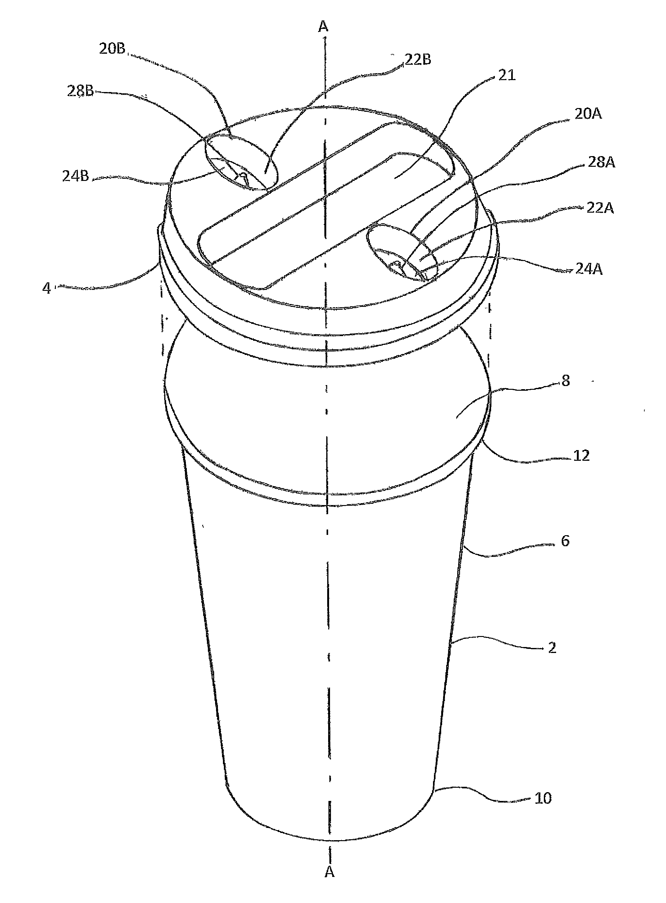
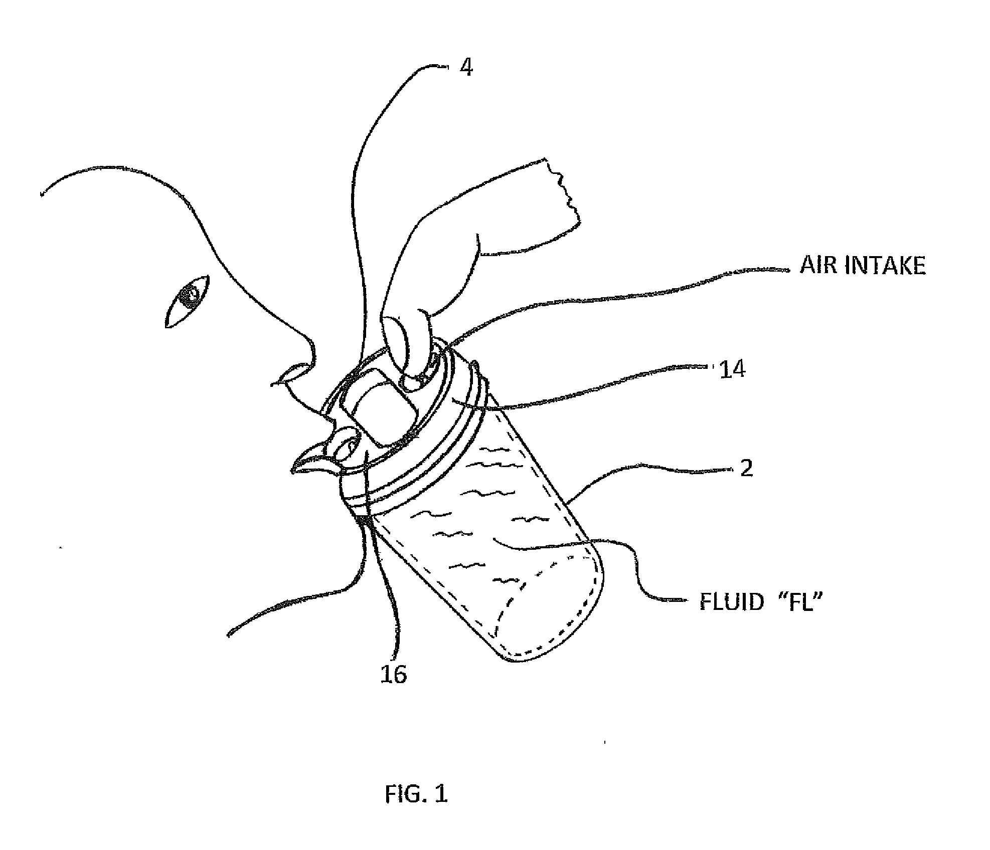
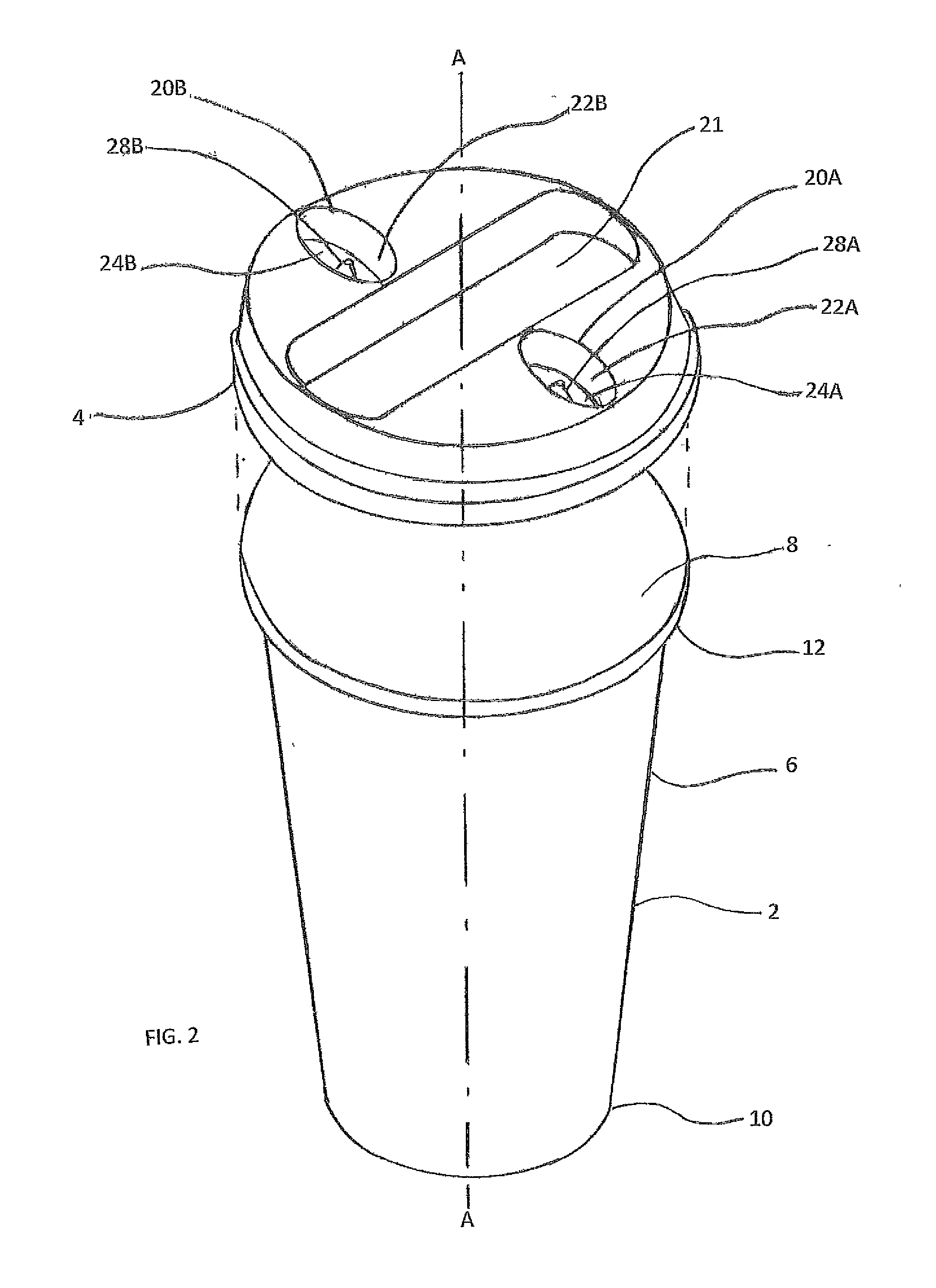
[0060]FIG. 1 is a perspective view of a fluid container 2 that utilizes a lid 4 according to an embodiment of the instant disclosure. In accordance with the instant disclosure, the lid 4, which defines a central axis “A-A” therethrough, enables a user to selectively dispense a fluid “FL” from fluid container 2 while maintaining a sealed engagement therewith when not dispensing fluid “FL” to prevent inadvertent spilling of the fluid “F.”

[0061]Fluid container 2 may be made from any suitable material including, but not limited to, plastic, paper, glass, metal, ceramic, closed-cell extruded polystyrene foam, cardboard, etc. Although fluid container 2 may have any suitable configuration, fluid container 2 is shown, for illustrative purposes, as a typical paper / cardboar...


PUM

PropertyMeasurementUnit
angleaaaaaaaaaa
pressureaaaaaaaaaa
heataaaaaaaaaa

Abstract

A lid configured for use with a fluid container includes a body member and a valve. The body member includes a central body that extends to an outer periphery configured to couple to a rim of a fluid container. The body member defines an aperture therethrough and has top and bottom surfaces. The valve has a first portion directly secured to the bottom surface and a second portion that extends from the first portion. The second portion includes a protuberance and is movable relative to the first portion between free and depressed states in response to deflection of at least a portion of the central body relative to the outer periphery. The protuberance is configured for sealed engagement with the aperture while the second portion is in the free state and is spaced from the aperture while the second portion is in the depressed state.

Description

TECHNICAL FIELD[0001]The present disclosure relates to fluid controlling devices and, more particularly, container lids and valves configured to couple to an open top of a fluid supporting container such as a beverage cup to selectively seal fluid within the fluid supporting container.BACKGROUND[0002]It has long been known in the prior art to enclose a container such as a cup with a lid selectively mounted to a rim of the cup. For example, lift-tabs or the like may be utilized to provide an opening in the lid for dispensing fluid contained within the cup. The lift-tab is typically perforated to allow a user to fold the lift-tab and secure the lift-tab to a corresponding protuberance provided on a top surface of the lid. However, one problem associated with the lift-tab type lids is that they are not resealable after having been folded.[0003]In comparison, known resealable container lids typically include complex mechanical mechanisms that are often an assembly of several distinct el...

Claims


Application Information

Patent Timeline
Patent Type & Authority Applications(United States)
IPC IPC(8): B65D51/16B65D43/06
CPCB65D51/1644B65D2543/00425B65D43/06B65D43/0212B65D47/247B65D47/32B65D51/1683B65D2543/00027B65D2543/00046B65D2543/00092B65D2543/00296B65D2543/00537B65D2543/00685B65D2543/00731B65D2543/00796Y10T29/49417Y10T29/49421B65D43/02
Inventor COLONERI, ANTONIO F.SEIDLER, JACK
Owner LIQUISTOP
Why Eureka
Try Eureka