
Manufacturing method for electrolyte membrane

a manufacturing method and electrolyte technology, applied in the direction of sustainable manufacturing/processing, non-metal conductor manufacturing, final product manufacturing, etc., can solve the problems of gas permeation through the space, limited operation temperature, and prone to cracking of electrolyte membrane, so as to facilitate bonding, reduce the sensitivity of proton conductivity, and polymerize the skeleton and the proton conducting material

Inactive Publication Date: 2005-01-27
EQUOS RES
View PDF8 Cites 5 Cited by
  • Summary
  • Abstract
  • Description
  • Claims
  • Application Information

AI Technical Summary

Benefits of technology

[0009] The present invention has been conceived of in the light of the above described problems, and aims to offer a solution by providing a manufacturing method for an electrolyte membrane that (a) has gas barrier properties and heat resisting properties, (b) can be operated in a low humidity atmosphere, and (c) can maintain proton conductivity even when the electrolyte membrane is used for a long period in conditions in which water, is present.
[0013] Accordingly, the manufacturing method for an electrolyte membrane of the present invention enables an electrolyte membrane to be manufactured that (i) has gas barrier properties and heat resisting properties, (ii) can be operated in a low humidity atmosphere, and (iii) can maintain proton conductivity even when the electrolyte membrane is used for a long period in conditions in which water is present.
[0015] The hydrocarbon-based polymer is used for the skeleton in order to (a) give the electrolyte membrane suitable flexibility, and (b) make handling and electrode formation easier. As the hydrocarbon-based polymer it is possible to utilize a polyether like poly-tetramethylene oxide, or a poly-methylene group.
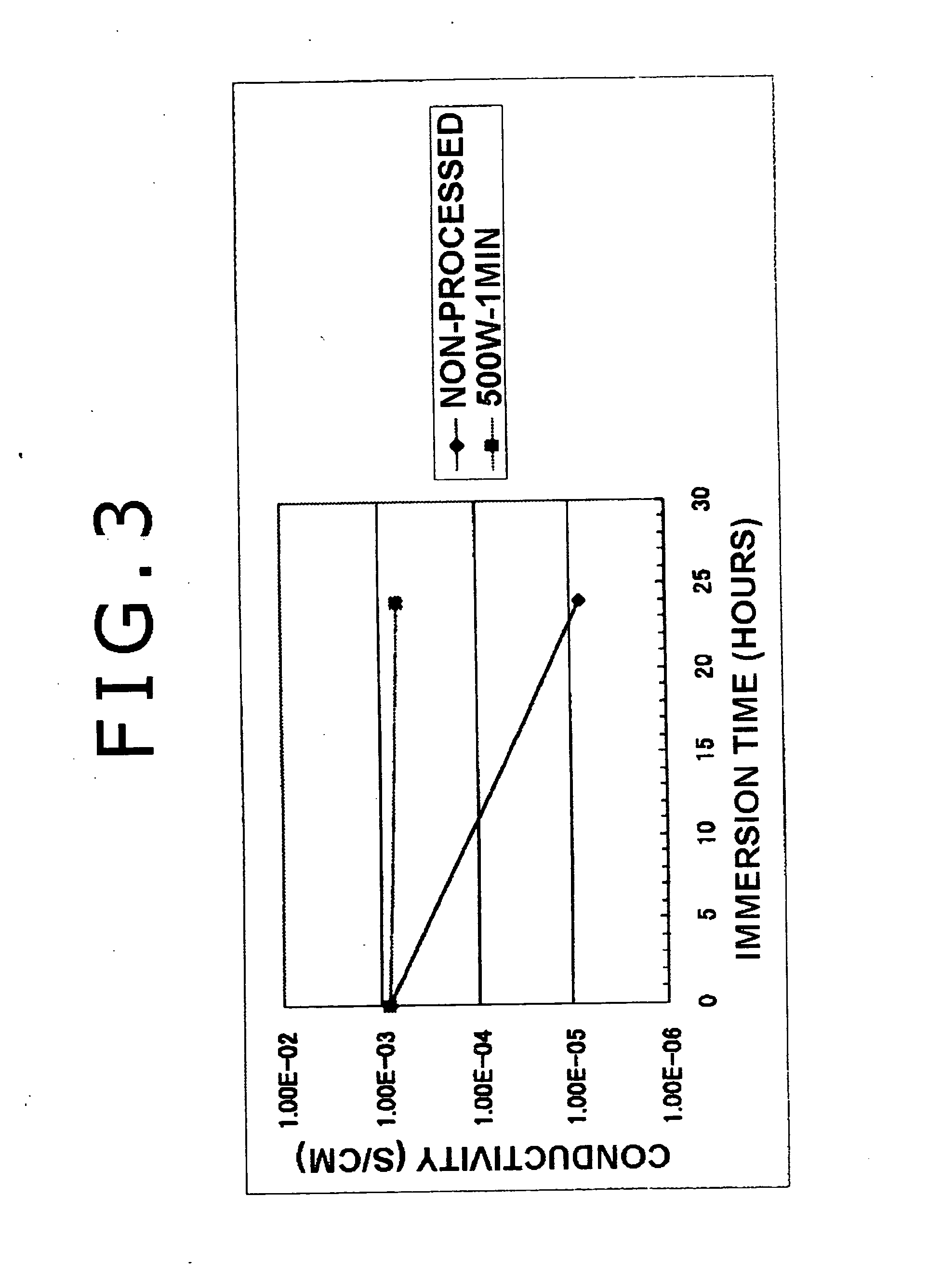
[0018] The intermediate product obtained in this manner includes an unreacted portion where the intermediate product dehydration polymerization reaction has not taken place. Accordingly, if this intermediate product is used in this form for a long time in conditions in which water is present, then proton conductivity is liable to reduce. Thus, according to the manufacturing method of the present invention, in the process step that follows forming of the intermediate product, microwaves with a wavelength that selectively imparts energy to the hydroxyl group included in the intermediate product are applied. As a result, intermediate product dehydration polymerization takes place in the unreacted portion, whereby it is possible to obtain an intermediate product that maintains proton conductivity even if used for a long time in conditions in which water is present.
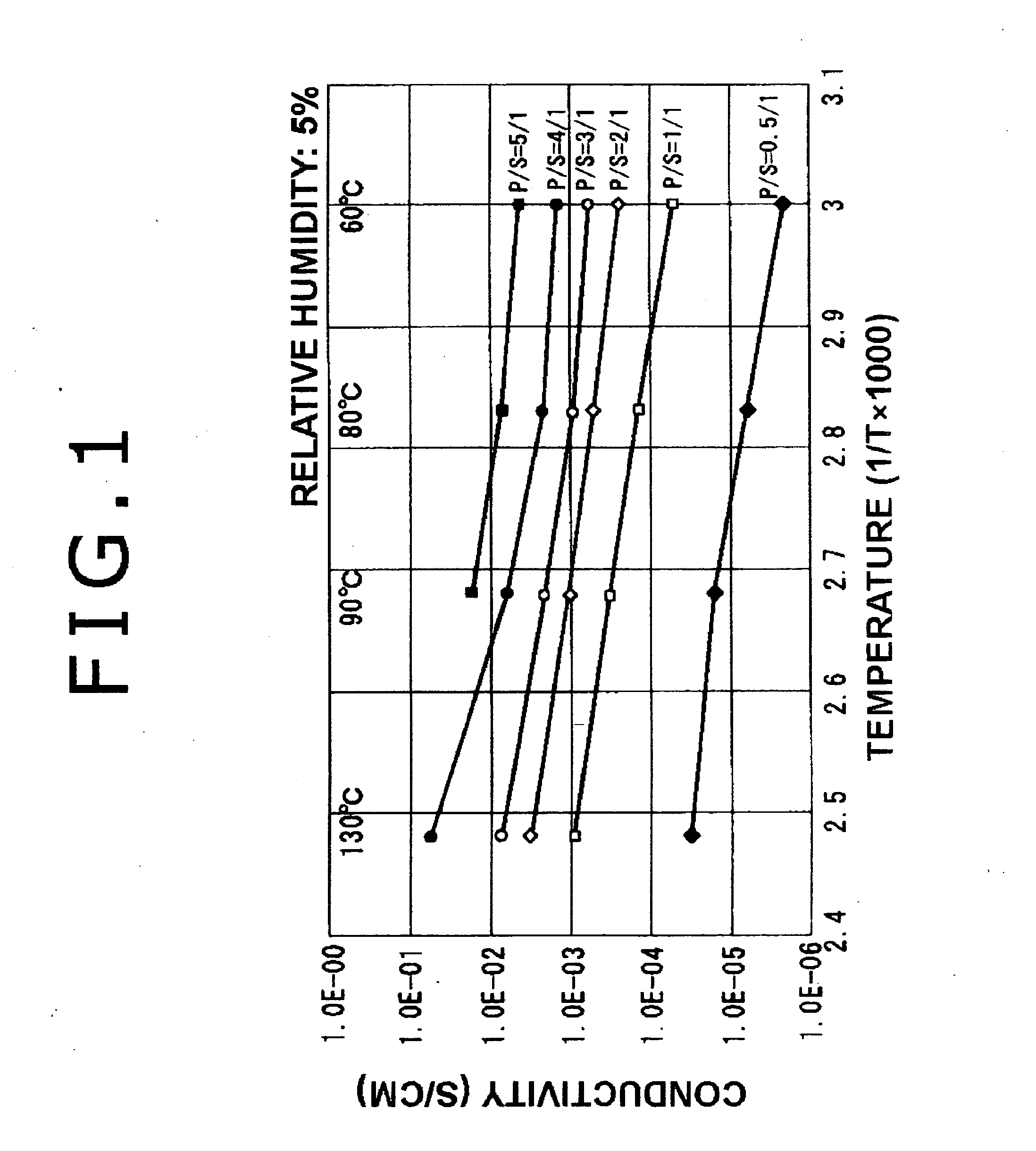
[0020] The electrolyte membrane obtained as a result of the above process is able to maintain proton conductivity even if used for a long period in conditions in which water is present. Moreover, this electrolyte membrane simultaneously demonstrate (a) gas barrier properties and flexibility due to the hydrocarbon-based polymer, and also (b) proton conductivity in the low humidity range due to the proton conducting material. In addition, the hybrid combination of the proton conducting material and the hydrocarbon-based polymer that forms the skeleton enables the electrolyte membrane to operate in a higher temperature range than conventional electrolyte membranes.

Problems solved by technology

However, when such fluorine membranes are utilized in an electrolyte membrane of a fuel cell or a sensor, the operation temperature is limited to 100° C. or less due to the heat resisting properties of the electrolyte membrane.
However, this electrolyte membrane is liable to crack, or the like, when humidity changes rapidly, and thus concerns have been raised about its durability when used in fuel cells, and so on.
However, the obtained electrolyte membrane has spaces present within it, which leads to difficulties related to permeation of gas through the spaces.
Accordingly, utilization of this electrolyte membrane in fuel cells in which a gas barrier must be maintained between an anode (an air electrode) and a cathode (a fuel electrode) is problematic.
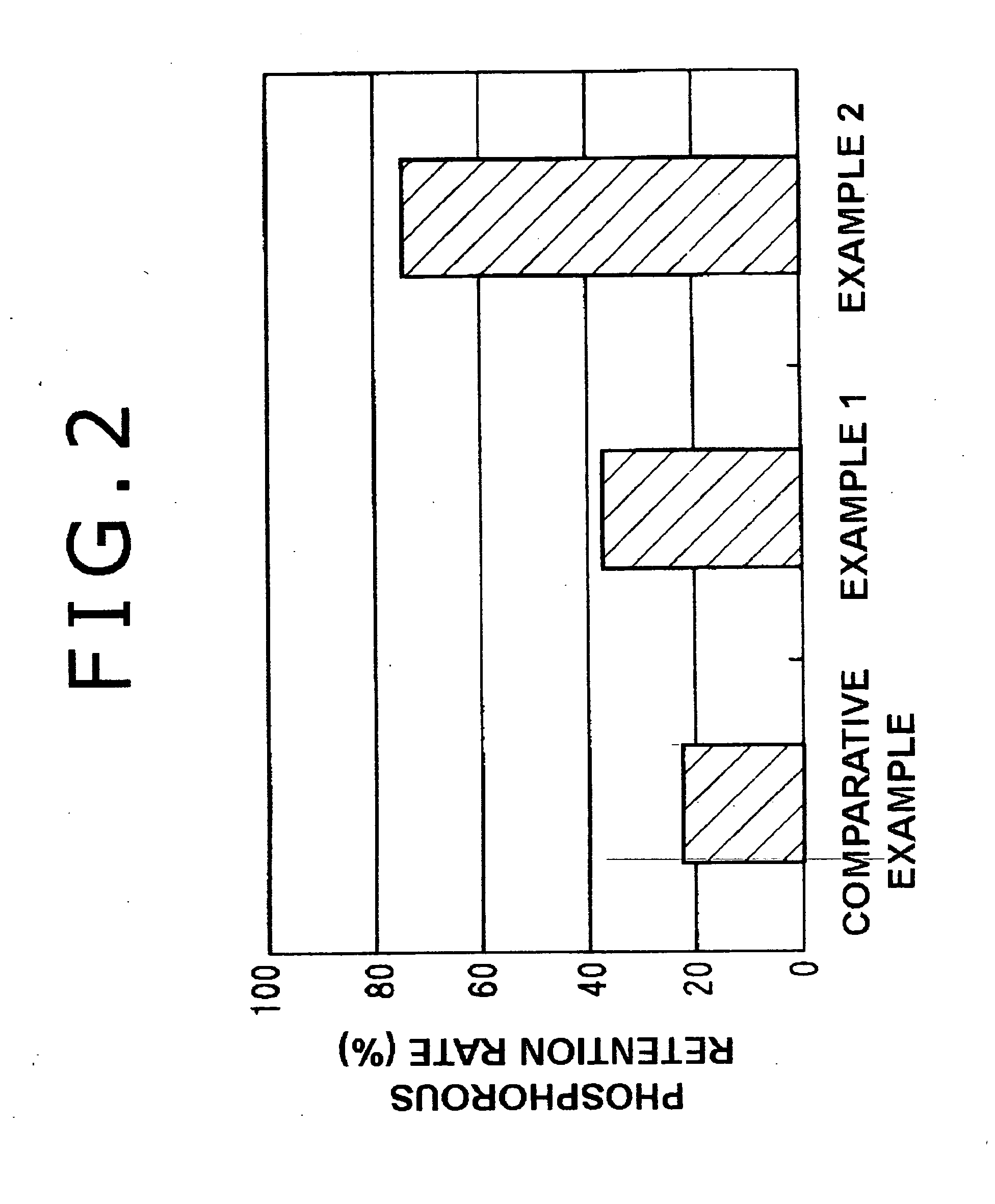
In this case, when the electrolyte membranes are used for a long period in conditions in which water is present the phosphoric acid is eluted into the water, whereby proton conductivity is impaired

Method used


Image

  • Manufacturing method for electrolyte membrane
  • Manufacturing method for electrolyte membrane
  • Manufacturing method for electrolyte membrane

Examples


Embodiment Construction

[0025] Hereinafter, a specific embodiment of the present invention will be described with reference to the drawings.

[0026] First Process Step

[0027] Polyethylene glycol (average molecular weight, 200 to 1000) was adopted for the hydrocarbon-based polymer. As shown in Formula 1, the polyethylene glycol and 3-isocyanate propyl-triethoxysilane were reacted at 60 degrees C in a tetrahydrofuran (TBF) solvent for forty-eight hours under a nitrogen atmosphere. Ethoxysilane group was then introduced by urethane bonding. Then, as indicated by Formula 2, a skeleton was obtained by introducing substituent.

H(OC2H4)nOH+2(C2H5O)3Si(CH2)3NCO  FORMULA 1

(C2H5O)3Si(CH2)3NHOC(OC2H4)nOCONH(CH2)Si(C2H5O)3   FORMULA 2

[0028] Next, the skeleton with the attached substituent was dissolved in ethanol, and water and phosphoric acid were added. The obtained solution was poured into a PTFE made petri dish. Then, hydrolysis and intermediate product dehydration polymerization of the solution were performed at...


PUM

PropertyMeasurementUnit
temperaturesaaaaaaaaaa
frequenciesaaaaaaaaaa

Abstract

In a first process step, intermediate product dehydration polymerization of a hydrocarbon-based polymer including a metal alkoxide and phosphoric acid is performed to obtain an intermediate product. Then, in a second process step, the intermediate product is irradiated by microwaves with a wavelength that selectively imparts energy to a hydroxyl group included in the intermediate product. As a result, an electrolyte membrane is obtained that is composed from a skeleton formed from a hydrocarbon-based polymer and phosphoric acid that is proton conductive.

Description

[0001] The disclosure of Japanese Patent Application No. 2003-277918 filed on Jul. 22, 2003 including the specification, drawings and abstract is incorporated herein by reference in its entirety. BACKGROUND OF THE INVENTION [0002] 1. Field of the Invention [0003] The present invention relates to a manufacturing method for an electrolyte membrane. [0004] 2. Description of the Related Art [0005] As general-use electrolyte membranes, fluorine-based membranes are known that have a basic skeleton of perfluoroalkylene group, with an ion exchange group like sulfone group or carbon group attached to the terminal of a perfluoro-vinylether side chain in one portion (for example, the Nafion R membrane of Du Pont (see U.S. Pat. No. 4,330,654). However, when such fluorine membranes are utilized in an electrolyte membrane of a fuel cell or a sensor, the operation temperature is limited to 100° C. or less due to the heat resisting properties of the electrolyte membrane. In addition, it is necessar...

Claims


Application Information

Patent Timeline
Patent Type & Authority Applications(United States)
IPC IPC(8): C08J5/22B01D67/00B01D69/14B01D71/52B01D71/82C08F2/46C08G2/00C08J3/28H01B1/06H01B13/00H01M8/02H01M8/10
CPCB01D67/009B01D69/141B01D71/52B01D71/82C08J5/2256H01M8/1027C08J2383/00H01M8/1037H01M8/1072H01M8/1074H01M2300/0082Y02E60/521H01M8/103Y02P70/50Y02E60/50B01D71/5211B01D69/1411
Inventor HASEGAWA, NORIFUMIHAYAKAWA, NANA
Owner EQUOS RES
Learn More