Electrically controlled ion transport device

a technology of electric control and ion transport, which is applied in the direction of filtration separation, lavatory sanitory, light and heating apparatus, etc., can solve the problems of unspecific delivery of ions, inability of available methods to provide controlled ion flux to cells, and little is known about the molecular and physiological effects of cells, etc., to achieve high volume production and low cost

Active Publication Date: 2012-03-20
OBOE IPR
View PDF9 Cites 17 Cited by
  • Summary
  • Abstract
  • Description
  • Claims
  • Application Information

AI Technical Summary

Benefits of technology

[0014]Thus, the invention involves limiting an electronic current, i.e. a current or flow of electrons, in a material, while maintaining the ion conductivity of the material. A limitation of the electronic current in the material can e.g. be achieved by limiting the electron conductivity. This limitation makes it possible to maintain a potential difference over the material when a voltage is applied across it. The potential difference can then be used as a driving force for ion transport from one portion of the material to another.
[0128]The configuration of the inventive device in some embodiments thereof, allows the device to be manufactured using well known conventional deposition methods, such as printing methods. This is of course very advantageous in that it enables high volume production at relatively low cost, which e.g. allows implementation of the device in affordable single use products.

Problems solved by technology

Due to technical limitations of available methods to decipher these complex signalling pathways, very little is known about the molecular and physiological effects on cells.
A limitation of certain concern is the inability of available methods to provide controlled ion fluxes to cells to be studied.
Such techniques result in unspecific delivery of ions to a cell culture medium as such only, whereas further diffusion to cells cultured in the medium is uncontrollable and unpredictable.
Furthermore, said techniques require the use of expensive equipment.

Method used


Image

  • Electrically controlled ion transport device
  • Electrically controlled ion transport device
  • Electrically controlled ion transport device

Examples


embodiment 1

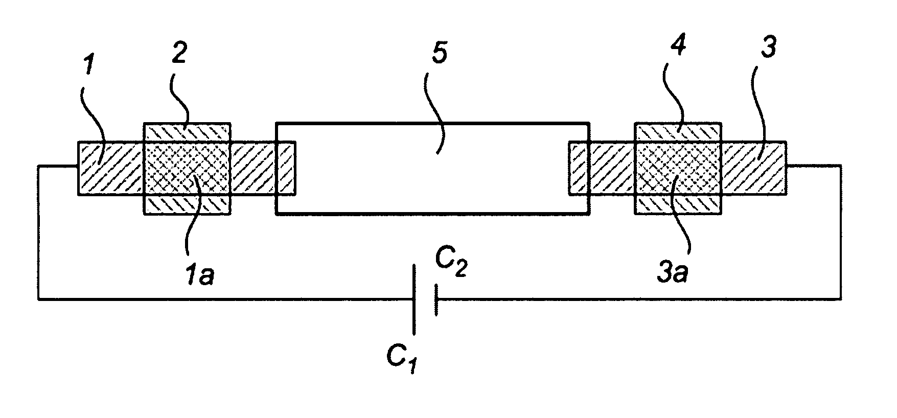
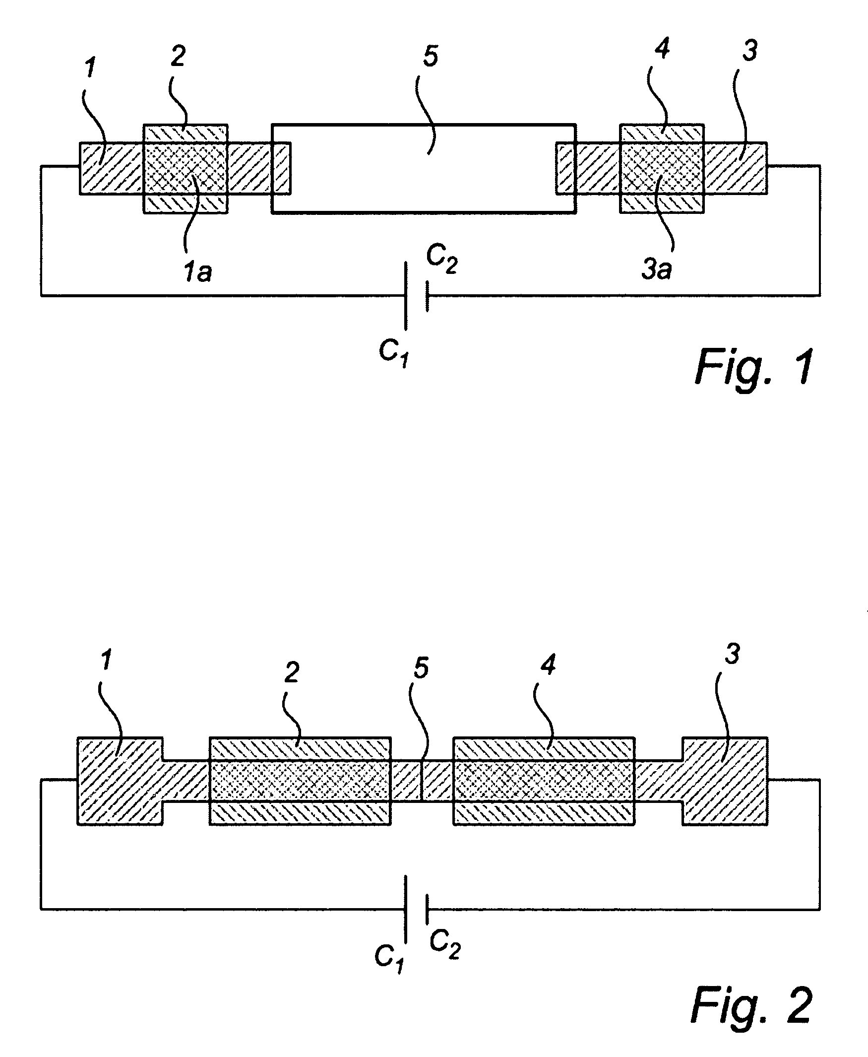
[0145]A schematic top-view of an ion transport device according to the invention is shown in FIG. 1. According to this embodiment device comprises a source electrode 1 and a target electrode 3, each capable of conducting ions and electrons. Said electrodes 1,3 have an elongated shape, are preferably arranged as layers and at a distance from each other, i.e. are not in direct physical contact with each other. A portion 1a of the source electrode 1 is in ionic contact with a portion of a source electrolyte 2, and a portion 3a of the target electrode 3 is in ionic contact with the target electrolyte 4. In other words, ions can be transported from said source electrolyte into said source electrode, and transported from said target electrode to said target electrolyte, respectively, by means of diffusion. According to one embodiment of the invention said electrolytes 2,4 are in direct physical contact with the respective electrode 1,3, and according to another embodiment a material capab...

embodiment 2

[0149]A second embodiment of the invention is schematically illustrated in FIG. 2. This embodiment is arranged as described in relation to FIG. 1, except that the source electrode 1, target electrode 3 and ion conductive channel 5 is made of a unitary piece of electrically conductive polymer material, wherein the ion-conductive channel 5 has been formed by rendering a portion of the polymer material electrically non-conducting, or at least essentially non-conducting by means of e.g. overoxidation, which portion is arranged between said source electrode 1 and said target electrode 3. In FIG. 2 the ion-conductive channel is illustrated as a thin line, but the length of the ion-conductive channel, as taken from said source electrode to said target electrode, can also be substantially longer.

embodiment 3

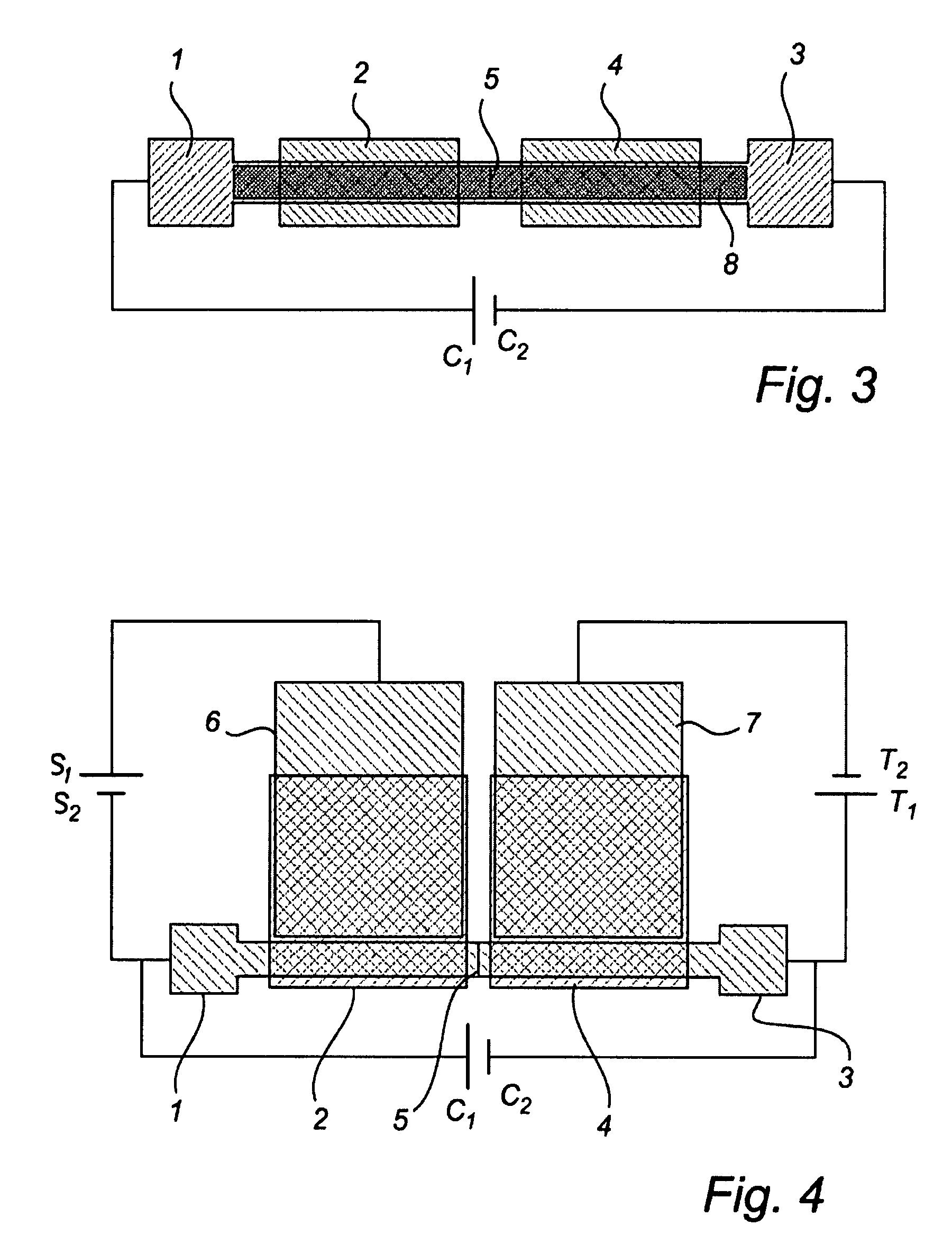
[0150]A third embodiment of the invention is schematically illustrated in FIG. 3. This embodiment is arranged as described in relation to FIG. 1 or 2, except that the ion conductive channel 5, the source electrode 1 and the target electrode 3 further comprises layer of a polymer hydrogel 8, which is arranged between the electrically conductive materials of the electrodes and a respective portion of the source and target electrolytes, such that in ionic contact between the source and target electrolyte and said respective portion of the polymer hydrogel is provided. The hydrogel layer increases ion transport from the first to the second electrolyte by providing an easily accessible pathway for ion transport.


PUM

PropertyMeasurementUnit
thicknessaaaaaaaaaa
voltageaaaaaaaaaa
voltageaaaaaaaaaa

Abstract

A device is disclosed for electrically controlled transport of ions between a source and a target electrolyte, including a source electrode and a target electrode. The electrodes are each capable of conducting ions, and the source electrode is arranged to receive ions from the source electrolyte and the target electrode is arranged to release ions to the target electrolyte. The device further includes an ion-conductive channel, arranged to receive ions from the source electrode and to release ions to the target electrode. Moreover, the ion-conductive channel is arranged to provide an ionic connection between the source and the target electrodes. The electrodes and the ion-conductive channel are formed of solid or semi-solid materials which are directly or indirectly attached to a support. In at least one embodiment, the device also includes a device for limiting an electronic current between the source and the target electrodes, such that at least after a voltage is applied across the channel a potential difference between the source and target electrodes is maintained, which potential difference effects ion transport from said source to the target electrode. An apparatus for transporting ions to or from a cell, use of the device for transporting ions to or from a cell, and methods of operating the device are also disclosed.

Description

PRIORITY STATEMENT[0001]The present application hereby claims priority under 35 U.S.C. §119 on European patent application number EP 06114939.9 filed Jun. 2, 2006, the entire contents of which is hereby incorporated herein by reference.FIELD OF THE INVENTION[0002]The present invention relates to a device for electrically controlled transport of ions between a source and a target electrolyte, and to an apparatus for transporting ions to or from a cell. The present invention further relates to the use of such a device for transporting ions to or from a cell, and to methods of operating such a device.BACKGROUND[0003]Ion signalling in eukaryotic cells is essential for numerous physiological processes, including regulation of exocytosis, contraction, gene transcription and fertilization, as well as maintenance of cell membrane potential. Ion signalling is equally important in prokaryotic cells, e.g. in osmoregulation. Ion signalling in cells may be affected by alteration of extracellular...

Claims


Application Information

Patent Timeline
Patent Type & Authority Patents(United States)
IPC IPC(8): B01D61/44
CPCG01N33/48728
Inventor BERGGREN, MAGNUSKJALL, PETERNILSSON, DAVIDROBINSON, NATHANIEL D.DAHLFORS, AGNETA RICHTERISAKSSON, JOAKIM
Owner OBOE IPR
Why Eureka
Try Eureka