
Contiguous capillary electrospray sources and analytical devices

a capillary electrospray and source technology, applied in the direction of centrifugal wheel fertilisers, separation processes, particle separator tube details, etc., can solve the problems of large dilution of eluting analytes, sensitivity suffers, and the limits of common detection techniques are particularly eviden

Active Publication Date: 2006-03-16
HEALTH & HUMAN SERVICES DEPT OF THE GOVERNMENT OF THE US SEC
View PDF82 Cites 18 Cited by
  • Summary
  • Abstract
  • Description
  • Claims
  • Application Information

AI Technical Summary

Benefits of technology

[0009] The inventions described herein enable one to obtain the mass spectra of macromolecular analytes, such as peptides, proteins, RNA, DNA, oligonucleotides, and polymers at concentrations lower than previously possibly. As provided herein, the present invention achieves one goal of providing new capillary designs that directly couple CE online with MS. New contiguous capillaries are provided that do not require a sheathed opening or break in the capillary near the spray tip. The new contiguous capillaries are not only rugged and simple in design, but they also effect an increase in macromolecular analyte detection sensitivity of up to about 100-fold in CE-ESI-MS devices—a veritable quantum leap in molecular detection technology.
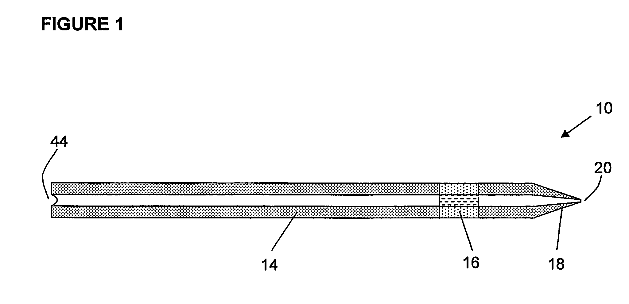
[0010] Thus, in a first aspect of the present invention, there are provided contiguous capillaries for electrospraying a fluid comprising analyte and electrolyte. In this aspect, each of the capillaries includes an inlet end to supply the fluid into the capillary, a spray tip for spraying fluid out of the capillary, and an electrically conductive portion of the capillary in proximity to the spray tip. In this aspect of the invention, the fluid containing the analyte enters the inlet end and exits the spray tip. Also, the electrically conductive portion is designed to minimize analyte loss while maintaining electrical conductivity.
[0011] In another aspect of the present invention, there are provided contiguous capillaries that are suitable for conveying fluid samples containing analytes into an analytical instrument. In this aspect of the invention, the contiguous capillaries include an inlet end to supply the fluid into the capillary, a spray tip for spraying fluid out of the capillary, and an electrically conductive portion of the capillary in proximity to the spray tip. In this aspect of the invention, the wall of the electrically conductive portion of the capillary is capable of blocking passage of analyte molecules therethrough.
[0012] In another aspect of the present invention there are provided electrospray sources, each including a contiguous capillary for separating and electrospraying a fluid comprising analyte and electrolyte. Here, each of the capillaries includes an inlet end to supply the fluid into the capillary, a spray tip for spraying fluid out of the capillary, and an electrically conductive portion of the capillary in proximity to the spray tip. In this aspect of the invention, the fluid containing the analyte enters the inlet end and exits the spray tip. The electrically conductive portion may provide a voltage along the capillary interior, at the spray tip, or both. The electrically conductive portion is designed to minimize analyte loss while maintaining electrical conductivity.
[0014] In various aspects of the invention, each capillary includes: an inlet end to supply a fluid into the capillary, the fluid comprising analyte and electrolyte; a spray tip to spray fluid out of the end of the capillary that is opposite to the inlet end; and an electrically conductive portion of the capillary in proximity to said spray tip. The electrically conductive portion may provide a voltage along the capillary interior, at the spray tip, or both. Also, the electrically conductive portion is designed to minimize analyte loss while maintaining electrical conductivity.
[0018] In these methods for conveying fluid into analytical instruments, each capillary includes: an inlet end to supply a fluid into the capillary, the fluid comprising analyte and electrolyte; a spray tip to spray fluid out of the end of the capillary that is opposite the inlet end; and an electrically conductive portion of the capillary in proximity to the spray tip. The electrically conductive portion provides a voltage along the capillary interior, at the spray tip, or both. Also, the electrically conductive portion is designed to minimize analyte loss while maintaining electrical conductivity.

Problems solved by technology

The limits of these common detection techniques are particularly evident in the identification and analysis of macromolecules, such as peptides and proteins.
Coaxial sheath flow is the basis of most commercial instruments, though it suffers in sensitivity.
The low sensitivity of a coaxial sheath flow CE design arises largely from the relatively high sheath flow compared to the flow from the CE capillary, resulting in not only a large dilution of the eluting analytes, but also in hindered desorption of ions due to the non-optimal electrospray that results at such high flow rates.
Coupling CE online with MS through a liquid junction arrangement requires tedious capillary alignment and end-to-end butting of the separation capillary and the spray tip.
Unfortunately, even under the best conditions, sensitivity is compromised by loss and spreading of sample analytes in the relatively large dead volume of the liquid junction.
Unfortunately, these breaks and openings result in analyte loss, disruption of the fluid flow path, disruption of the electric field, or a combination of these effects near the spray tip, which ultimately degrades mass detection sensitivity.
Although these approaches do produce operational interfaces, their fabrication requires delicate manipulation of miniaturized components and they suffer in their robustness.
Furthermore, these junctions often suffer from misalignment and imperfect butting of the two pieces of capillary.
Single capillary methods appear to disrupt the CE separation the least, however, metal coatings on fused silica capillaries are not durable and drilling pin-holes through capillary walls is a delicate and irreproducible procedure.

Method used


Image

  • Contiguous capillary electrospray sources and analytical devices
  • Contiguous capillary electrospray sources and analytical devices
  • Contiguous capillary electrospray sources and analytical devices

Examples


examples

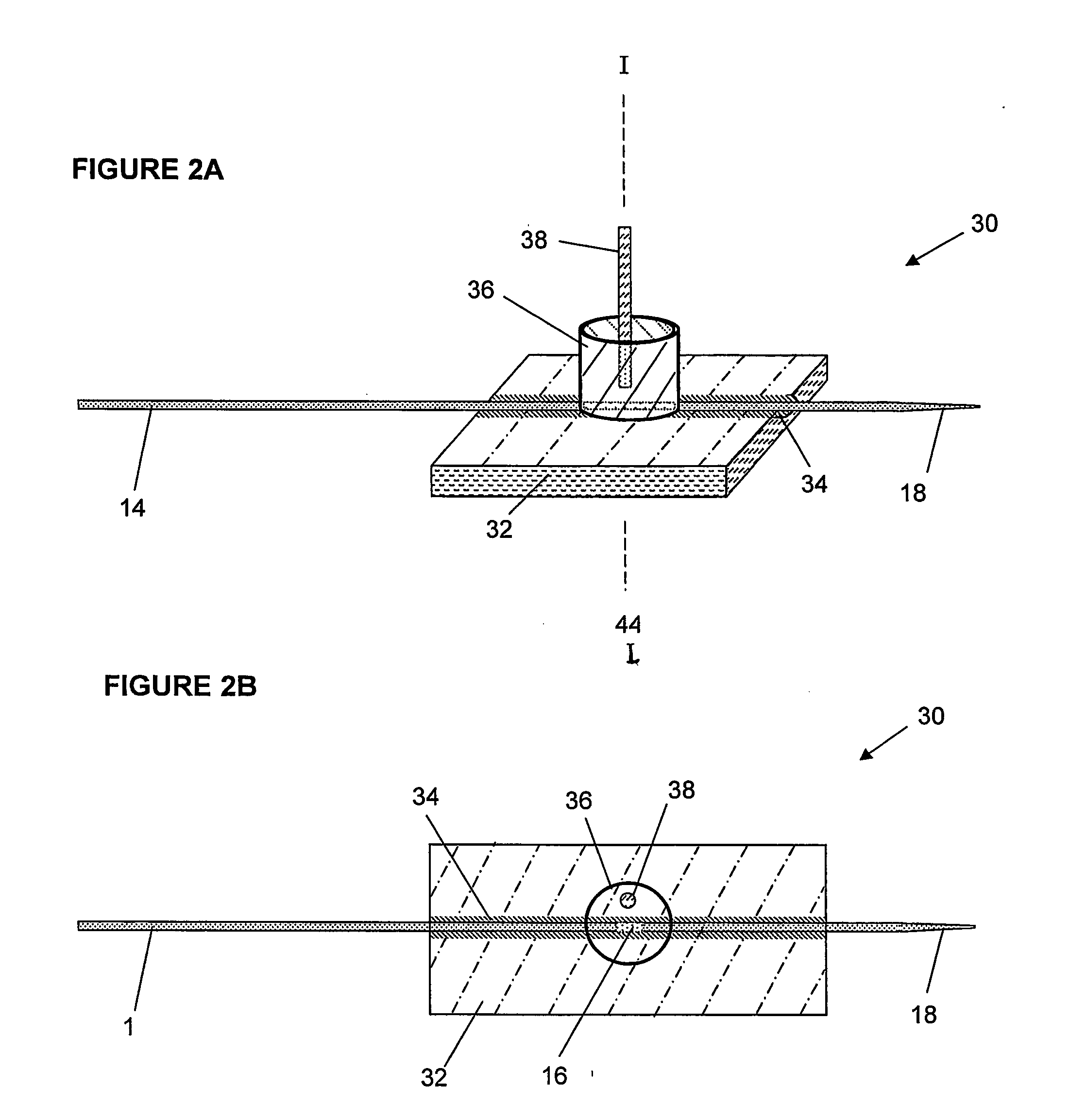
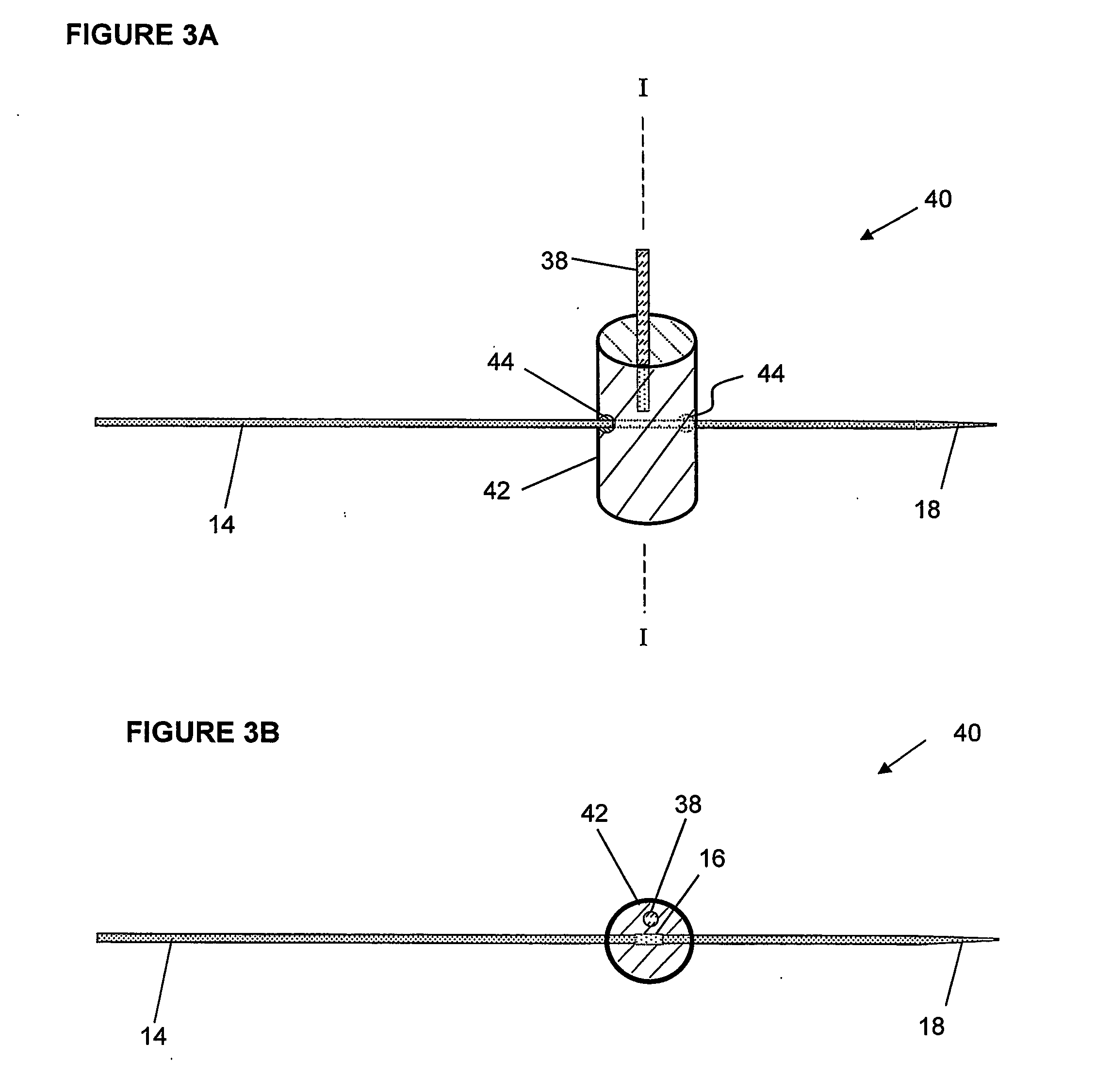
[0081] Contiguous capillaries. The following procedure describes the fabrication the contiguous capillary electrospray sources prepared from commercially available polyimide-coated fused silica capillaries (Polymicro Technologies, Phoenix, Ariz.). A spray tip was prepared by heating the capillary (75 cm long, 360 μm o.d., 50 μm i.d.) near the spray tip end with a microtorch and pulling it to draw down the inside diameter of the capillary to approximately 25 um. The polyimide coating was partially removed from a 3˜4 mm section of the capillary at a distance of 5 cm from the spray tip, to provide a partially (⅓) circum-etched capillary. The capillary was trimmed to a total length of 60 cm, and was mounted on an electrospray assembly as shown in FIGS. 2A and 2B. The assembly was constructed from a 4.5 cm×1.5 cm acrylic plastic substrate with a channel milled along its length having a depth that was slightly larger than the capillary diameter, and a 1.5 cm×1 cm i.d. acrylic plastic rese...


PUM


Abstract

Contiguous capillaries useful for separating and electrospraying a fluid comprising analyte and electrolyte are provided. The contiguous capillaries have spray tips at one end of the capillaries and electrically conductive portions in proximity to the spray tips. Methods for making the contiguous capillaries and their use as electrospray sources are also disclosed. Apparatus and methods for conveying analyte ions from the capillaries into analytical instruments, such as a mass spectrometer, are also disclosed. The disclosed contiguous capillaries may be used to carryout electrophoresis separation and electrospray ionization of analytes. Methods for obtaining the mass spectra of macromolecular analytes at concentrations lower than previously possibly are provided using the apparatus and procedures described herein.

Description

CROSS REFERENCE TO RELATED APPLICATIONS [0001] This application claims benefit of U.S. Provisional Application Ser. No. 60 / 420,003, filed Oct. 21, 2002, incorporated by reference herein in its entirety.GOVERNMENT RIGHTS [0002] The work leading to the disclosed inventions was finded in whole or in part with Federal funds from the National Cancer Institute, National Institutes of Health, under Contract No. NO1-CO-12400. Accordingly, the U.S. Government has rights in these inventions.FIELD OF THE INVENTION [0003] The present inventions are related to the field of molecular analysis of fluids comprising analyte and electrolyte using capillaries. Related are inventions for devices and methods for electrospraying analyte ions from capillaries into analytical instruments, such as a mass spectrometer. The capillaries may be used in the electrophoresis separation of, and in the electrospraying of analytes. BACKGROUND OF TH INVENTION [0004] Mass spectrometry (MS) is arguably among the most us...

Claims


Application Information

Patent Timeline
IPC IPC(8): C12M1/34C12Q1/00A01C17/00B01D57/02B05B5/025B05B5/053C02F1/40H01JH01J7/24H01J49/04
CPCB05B5/0255B05B5/0533H01J49/167G01N35/1095H01J49/04G01N27/44717
Inventor JANINI, GEORGEISSAQ, HALEEMVEENSTRA, TIMOTHYCONRADS, THOMASWILKENS, KENNETH
Owner HEALTH & HUMAN SERVICES DEPT OF THE GOVERNMENT OF THE US SEC
Learn More