A stirrup iron

a stirrup iron and stirrup technology, which is applied in the field of stirrup irons, can solve the problems of affecting the safety of standing on an object to mount a horse, affecting the safety of riding, so as to reduce the tendency of the stirrup iron to be opened inadvertently

Inactive Publication Date: 2015-11-19
HORSEWARE PRODS
View PDF9 Cites 4 Cited by
  • Summary
  • Abstract
  • Description
  • Claims
  • Application Information

AI Technical Summary

Benefits of technology

[0018]By having such a stirrup iron, the stirrup iron will provide a step to facilitate mounting of the horse. The step is integral with the remainder of the stirrup iron and a separate piece of kit is not required. Once the rider's foot is placed on the foot plate, the stirrup iron will automatically assume a closed loop configuration. The rider will not have to adjust buckles, straps or other devices and they will at no stage have to take their hands off the reins in order to close the stirrup iron. Furthermore, the configuration of stirrup iron will not have a tendency to pinch or otherwise harm or startle the animal as it assumes the closed loop configuration. Advantageously, the stirrup iron will not have a tendency to inadvertently open during use as the weight of the rider acts to close the stirrup iron. In addition to the above, the performance of the stirrup iron will not be affected to the same degree by the ingress of dirt and will not have the same tendency to degrade over time as the components age.
[0019]In one embodiment of the invention there is provided a stirrup iron in which the cam mechanism comprises a single connector link arm mounted at one end to the foot plate and pivotally mounted at its other end to the connector arm. This is seen as a simple construction of device that will be relatively inexpensive to manufacture and reliable in operation.
[0023]In one embodiment of the invention there is provided a stirrup iron in which one side of the step portion that is intended for engagement of a riders boot is provided with a non-slip surface. This is seen as particularly useful as the surface on which the rider's boot will be located will provide grip to the rider's boot assisting in their mounting of the horse and obviating the possibility of the rider slipping.
[0024]In one embodiment of the invention there is provided a stirrup iron in which the non-slip surface is provided by way of a serrated surface. This is seen as a simple inexpensive way of providing grip that can be incorporated into the moulding or casting of the stirrup iron.
[0026]In one embodiment of the invention there is provided a stirrup iron in which the catch mechanism is provided with a release button that is recessed into the two part construction to avoid inadvertent release of the releasable locking mechanism. By having a release latch recessed into the two part construction, there will be far less tendency for the stirrup iron to be opened inadvertently.

Problems solved by technology

However, when the stirrups are at a suitable length for riding, many riders experience difficulty in elevating their foot to the height of the stirrup iron in order to mount the horse.
Depending on the height of the horse or the rider, it may prove difficult to mount the horse while the stirrups are at a shortened riding length.
However, standing on an object to mount a horse is not safe as the horse can move away from the object unexpectedly.
Additionally, in many instances, such as where a horse is nervous or excited, it can prove difficult to keep the horse standing beside an object to allow a rider to mount safely.
Furthermore, such objects may not always be available when out riding.
However, a second person may not always be present to assist the rider in mounting, for example in situations where the rider is out hunting or hacking.
However, once the rider has mounted it can prove difficult to adjust the stirrup to the correct riding length while astride the horse.
Furthermore, inexperienced riders may have difficulty in maintaining control of their horse while holding the reins in one hand and adjusting the stirrup length with their other hand.
Additionally, in some instances the stirrup leather may not allow sufficient lengthening to assist mounting.
Generally speaking, adjustment of the stirrup leather while mounted on a horse is difficult, time consuming and undesirable to do.
However, this has the disadvantage that the stirrup may open while riding if the rider inadvertently places too much pressure from their foot against the outside of the stirrup.
Additionally, the spring mechanism to allow pivoting of the mounting step may lose resilience over time or become rusted or clogged with dirt thereby preventing correct operation.
However, as this device pivots upwards to a closed position once the rider has mounted, it is liable to brush off the body of the horse which may startle or pinch the animal.
Furthermore, the horse may incorrectly interpret this as a signal from the rider to move forwards.
Although such a device will initially assist the rider in mounting, they may experience difficultly should they have to dismount and remount as it is not practical to carry such a device while riding.

Method used


Image

  • A stirrup iron
  • A stirrup iron
  • A stirrup iron

Examples


Embodiment Construction

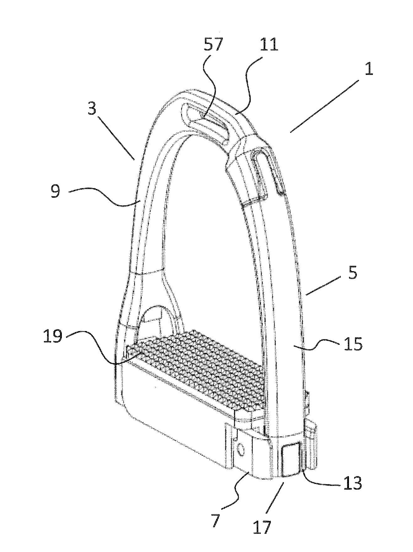
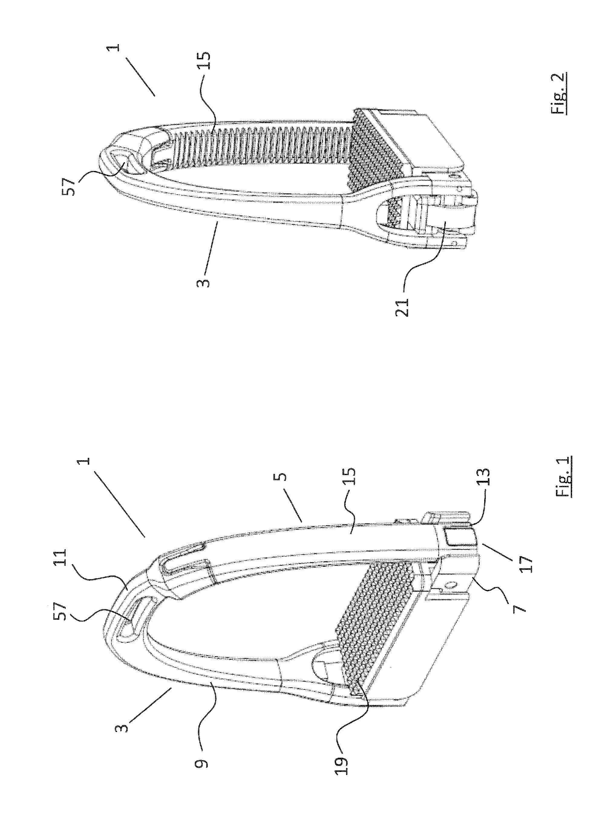
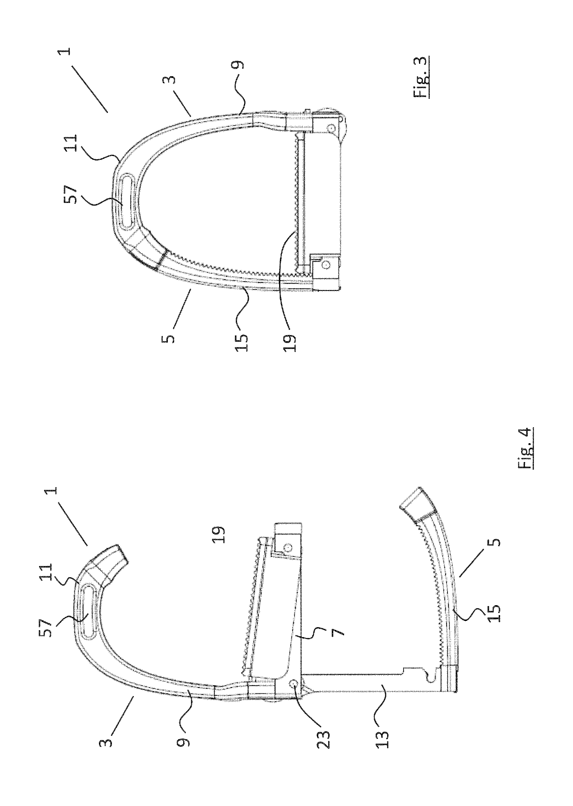
[0059]Referring to FIGS. 1 to 16 inclusive, there is shown a stirrup iron, indicated generally by the reference numeral 1, comprising a two part construction including a first, fixed part 3, and a second, moveable part 5 that is moveable relative to the fixed part 3. In the embodiment shown, the first fixed part 3 comprises a substantially C-shaped body having a base plate 7, a side upright 9 and a top plate 11. The side upright 9 is connected to the base plate adjacent one, innermost end thereof and the top plate is connected at one of its ends to the uppermost end of the side upright. The top plate 11 extends outwardly from the side upright 9 above and spaced apart from the base plate 7. The moveable part 5 comprises a substantially L-shaped arm having a connector portion 13 pivotally mounted to the fixed part 3 at one end thereof, and a step portion 15 extending substantially orthogonal to the connector portion 13. The stirrup iron 1 further comprises a releasable locking mechani...


PUM


Abstract

This invention relates to a stirrup iron (1) comprising a two part construction including a first, fixed part (3), and a second, moveable part (5). The fixed part (3) comprises a body and the moveable part (5) comprises an L-shaped arm pivotally mounted to the fixed part (3).The moveable part (5) is pivotable to and from a first operating position in which a step portion (15) of the moveable part (5) forms a closed loop stirrup, and a second operating position in which the step portion (15) is located below and spaced apart from the fixed part (3) thereby forming a foot-step. The stirrup iron (1) further comprises a releasable locking mechanism, a foot plate (19) mounted on the fixed part (3) and a cam mechanism connecting the foot plate (19) to the moveable part (5). Depression of the foot plate (19) will cause the cam mechanism to act on the moveable part (5) urging it from the second operating position towards the first operating position.

Description

TECHNICAL FIELD[0001]This invention relates to a stirrup iron for assisting a rider mounting a horse (or other equine).BACKGROUND ART[0002]A pair of stirrups is typically provided on a saddle to assist a rider in mounting a horse and to help maintain their balance while riding the horse. Stirrups usually comprise a stirrup iron, where a rider places their foot, connected to the saddle by an adjustable strap known as a stirrup leather. The length of the stirrups can be adjusted to suit the length of the rider's legs or the riding activity by either shortening or lengthening the stirrup leather.[0003]Traditionally, a rider will mount a horse from the left side, or near side, of the animal by elevating their left foot, inserting it into the left stirrup iron and then lifting themselves onto the saddle by placing their weight onto their left foot. However, when the stirrups are at a suitable length for riding, many riders experience difficulty in elevating their foot to the height of th...

Claims


Application Information

Patent Timeline
Patent Type & Authority Applications(United States)
IPC IPC(8): B68C3/02
CPCB68C3/02B68C3/00B68C2003/0025
Inventor BOWE, CHRISTOPHER
Owner HORSEWARE PRODS
Why Eureka
Try Eureka