Loop cutting apparatus for circular knitting machines

a cutting apparatus and circular knitting technology, applied in knitting, weft knitting, textiles and papermaking, etc., can solve the problems of increasing the total size the number of components, increasing the complexity of the circular knitting machine, and increasing the difficulty of fabrication and assembly, so as to achieve the effect of reducing the efficiency of knitting

Inactive Publication Date: 2015-11-19
PAI LUNG MACHINERY MILL CO LTD
View PDF27 Cites 5 Cited by
  • Summary
  • Abstract
  • Description
  • Claims
  • Application Information

AI Technical Summary

Benefits of technology

[0013]The yarn cutting apparatus of the invention can have the yarn cutting needle sets selectively mounted onto the circular cylinder or the upper needle dial. Through the movable first cutter needle and second cutter needle in each yarn cutting needle set, the yarn of the pile loop is in contact at the same time with the first cutter section of the first cutter needle and second cutter section of the second cutter needle, and is shorn at two sides to sever the pile loop. Compared with the conventional circular knitting machines for knitting fine pile fabrics, the invention does not need an extra sinker holder to guide the sinkers and also does not need to extend the travel path of the cutter needle, thus space utilization of the circular knitting machine is more efficient and the efficiency of knitting the fine pile fabrics also improves.

Problems solved by technology

However, the conventional circular knitting machines that can produce fine pile fabrics require to add a sinker holder around the cylinder, hence significantly increase the total size of the circular knitting machines and the number of components required.
As a result, the circular knitting machines are complex in structure, and fabrication and assembly also are more difficult.
However, in order to push the cutter needle to the apex its travel path has to increase, that means that the time to cut each pile loop is longer, that adversely affects the knitting efficiency of the fine pile fabrics.

Method used


Image

  • Loop cutting apparatus for circular knitting machines
  • Loop cutting apparatus for circular knitting machines
  • Loop cutting apparatus for circular knitting machines

Examples


Embodiment Construction

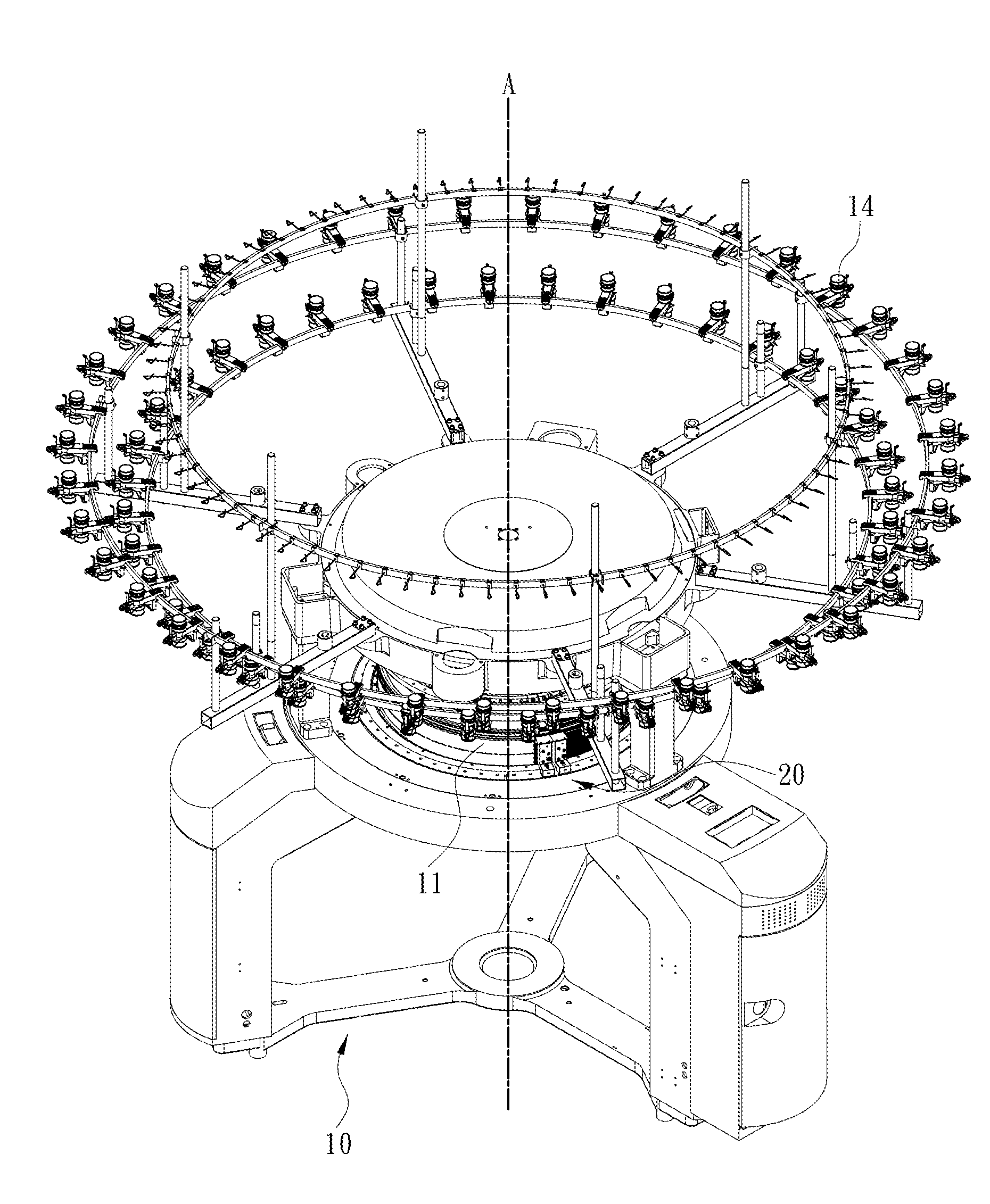
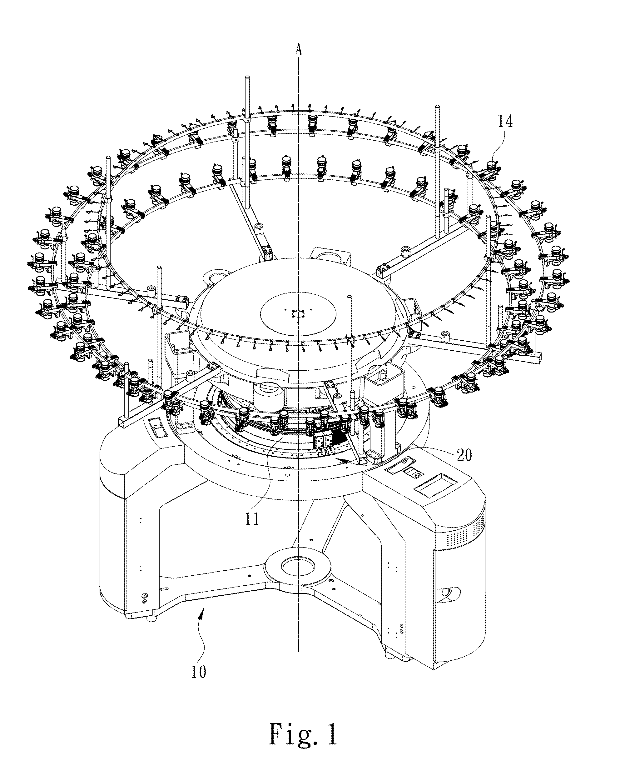
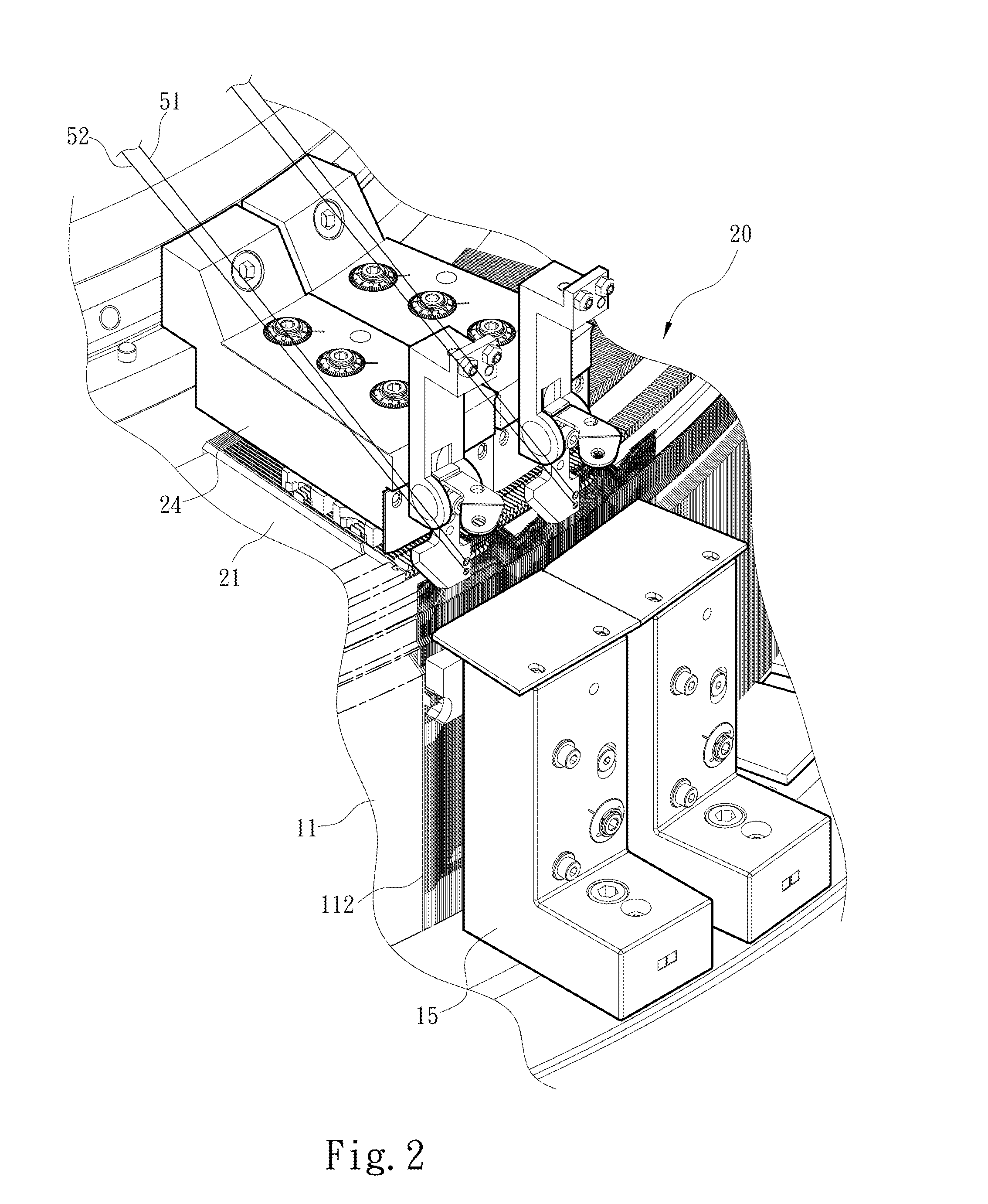
[0022]Please refer to FIGS. 1 through 4 for an embodiment of a loop cutting apparatus of the invention adopted on a circular knitting machine. The loop cutting apparatus 20 of the invention is used on a circular knitting machine 10 to knit fine pile fabrics which have a pile surface and a ground fabric to hold the pile surface. The circular knitting machine 10 has a circular cylinder 11 with an axis A and a yarn conveying system 14 to provide a plurality of yarns to the circular cylinder 11. The yarns include at least one first yarn 51 (generally called pile yarn) to form the annular yarn surface and at least one second yarn 52 (generally called ground yarn) to form the ground fabric. The circular cylinder 11 has a plurality of first needle slots 111 parallel with the axis A of the circular cylinder 11 and a plurality of knitting needles 112 located in the first needle slots 111 and movable independently. In this invention the knitting needles 112 can be moved and controlled through...


PUM


Abstract

A loop cutting apparatus for a circular knitting machine which has a circular cylinder including a plurality of knitting needles movable independently includes an upper needle dial located on the circular cylinder and a plurality of yarn cutting needle sets radially centered about the axis of the circular cylinder. Each yarn cutting needle set includes a first cutter needle and a second cutter needle movable against the first cutter needle in a first yarn cutting displacement thereof. The first cutter needle has a yarn holding section leaned by a yarn and collaborated with the two abutting knitting needles at two sides to pick up and draw the yarn to form a pile loop and a first cutter section connected to the yarn holding section. The second cutter needle has a second cutter section staggered against the first cutter section in the first yarn cutting displacement to cut the pile loop.

Description

FIELD OF THE INVENTION[0001]The present invention relates to a loop cutting apparatus for circular knitting machines and particularly to a loop cutting apparatus for circular knitting machines that cuts a pile loop immediately after it is formed.BACKGROUND OF THE INVENTION[0002]Fabrics with fine pile provide the look and touch feel of furs or pelts, hence are appealing to consumers. Conventional circular knitting machines that can knit fine plush fabrics, like U.S. Pat. Nos. 7,146,829 and 7,127,920, include a cylinder with a plurality of latch-less needles located thereon, a needle dial contained a plurality of latch needles and a plurality of sinkers. The sinkers are located on a sinker holder circulating the cylinder. Each sinker has a cutter at the front end. The sinker is driven by a cam on the sinker holder to slide toward the cylinder, and the cutter on the sinker severs a pile loop formed by a yarn to form a pile. References of other types of circular knitting machines that c...

Claims


Application Information

Patent Timeline
Patent Type & Authority Applications(United States)
IPC IPC(8): D04B9/12D04B15/60
CPCD04B15/60D04B9/12D04B15/68
Inventor YU, JEN WEI
Owner PAI LUNG MACHINERY MILL CO LTD
Why Eureka
Try Eureka