Liquid crystal display device

a liquid crystal display and display device technology, applied in the field of liquid crystal display devices, can solve problems such as prone to deterioration of viewing experience, and achieve the effect of low viewing angle dependen

Active Publication Date: 2015-11-19
SHARP KK
View PDF2 Cites 2 Cited by
  • Summary
  • Abstract
  • Description
  • Claims
  • Application Information

AI Technical Summary

Benefits of technology

[0020]According to the aspect of the invention, it is possible to provide a liquid crystal display device having low viewing-angle dependency without application of a complicated circuit structure.

Problems solved by technology

On the other hand, when the display screen is viewed from an oblique direction, contrast decreases, and thus viewability is apt to deteriorate.

Method used


Image

  • Liquid crystal display device
  • Liquid crystal display device
  • Liquid crystal display device

Examples


first embodiment

[0075]Hereinafter, an embodiment of the invention will be described with reference to FIG. 1 to FIG. 9D.

[0076]In this embodiment, a liquid crystal display device provided with a transmissive liquid crystal panel will be described as an example.

[0077]In addition, in the following drawings, so as to easily recognize respective constituent elements, dimensional scales may be made different in some constituent elements.

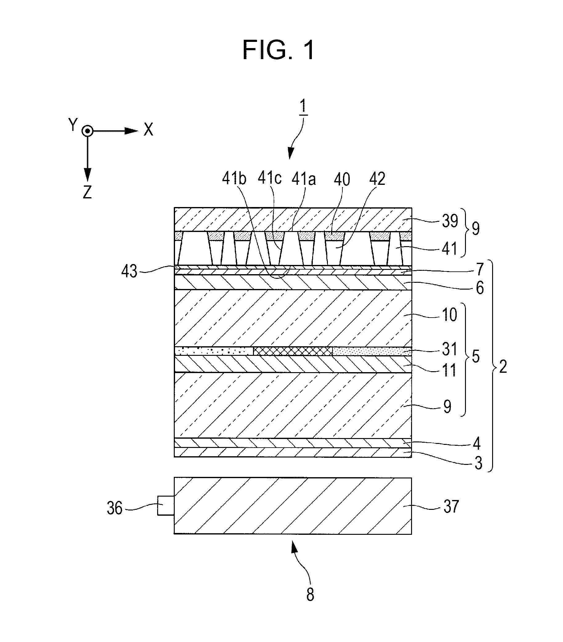
[0078]FIG. 1 is a cross-sectional view of a liquid crystal display device 1 of this embodiment.

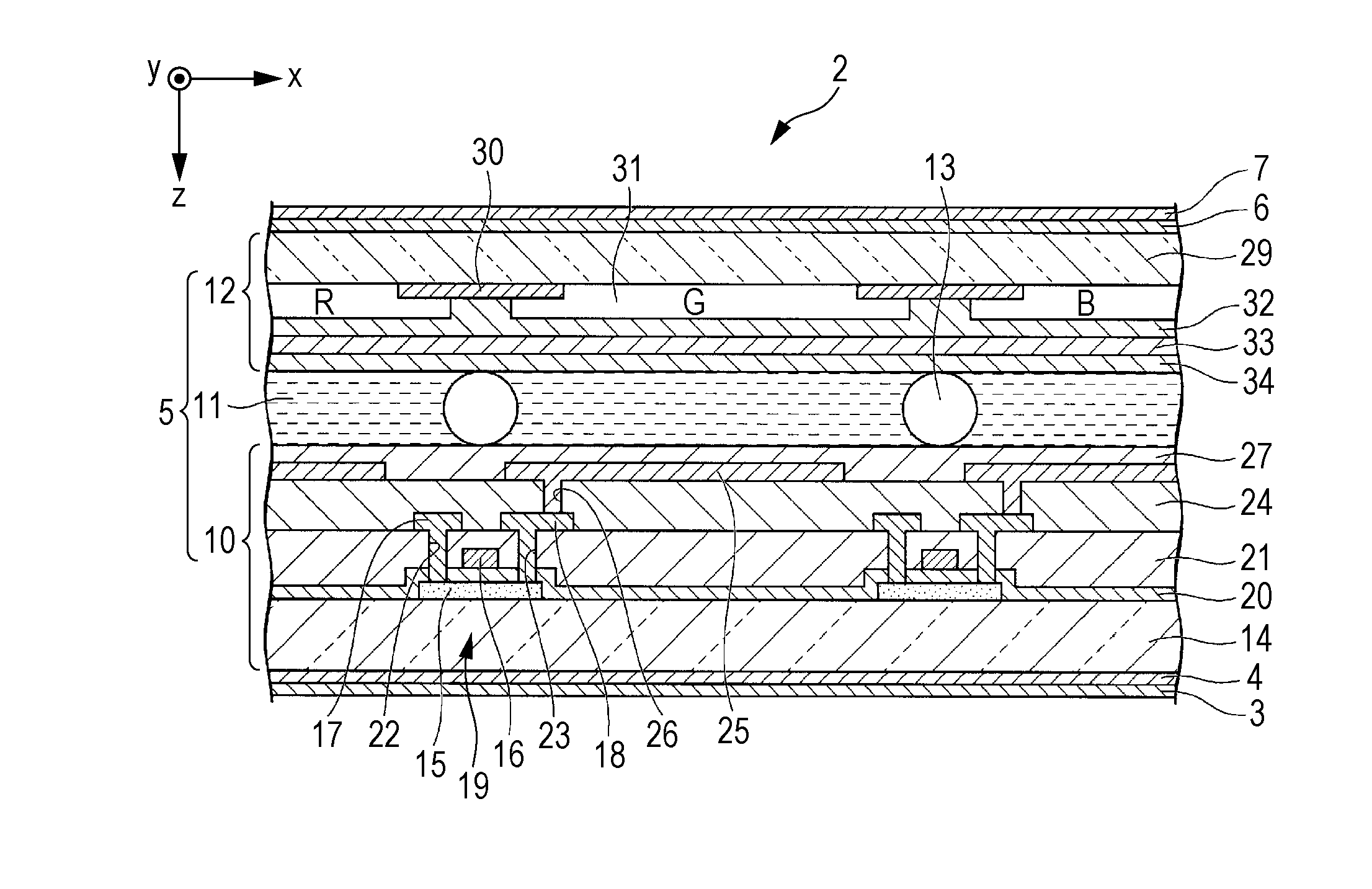
[0079]As illustrated in FIG. 1, the liquid crystal display device 1 of this embodiment includes a liquid crystal panel 2, a backlight 8 (illuminating device), and a light control member 9 (light control member). The liquid crystal panel 2 includes a first polarizing plate 3, a first retarder 4 (phase plate), a liquid crystal cell 5, a second retarder 6 (phase plate), and a second polarizing plate 7. In FIG. 1, the liquid crystal cell 5 is schematically illustrated, but a detaile...

second embodiment

[0186]Hereinafter, a second embodiment of the invention will be described with reference to FIG. 10.

[0187]The basic configuration of a liquid crystal display device of this embodiment is the same as in the first embodiment except that a plurality of light-diffusing portions 341 are arranged in a light control member 309. According to this, in this embodiment, the light control member 309 will be described.

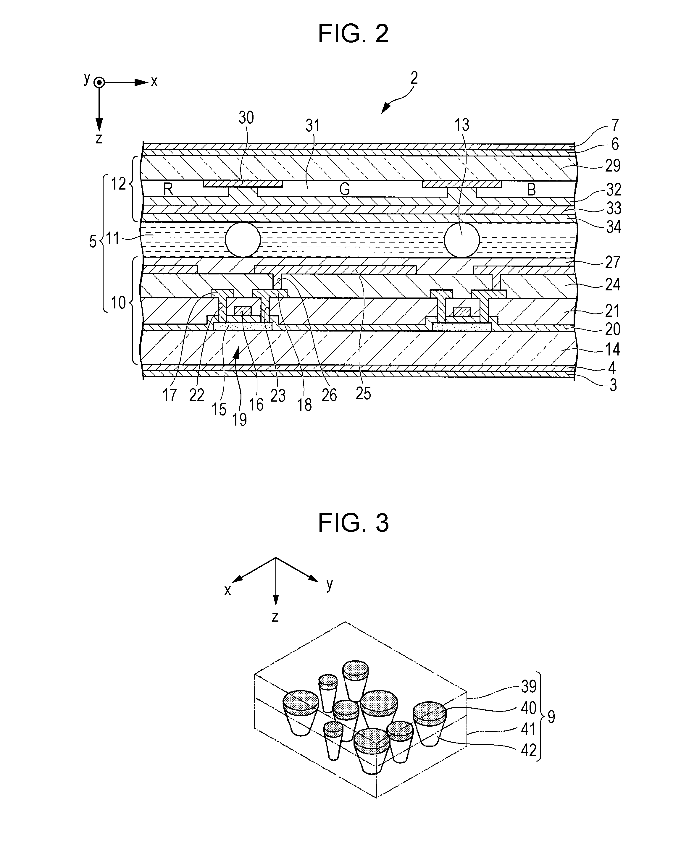
[0188]FIG. 10 is a top view of the light control member 309. As illustrated in FIG. 10, in the light control member 309 of this embodiment, a plurality of light-diffusing portions 341 are provided on one surface of the base material in a scattered manner. The planar shape of the light-diffusing portion 341 viewed from the normal direction of the base material is a circular shape.

[0189]A portion, which corresponds to a lower side of a light-shielding layer 340, becomes a hollow portion 342. Air exists in the hollow portion 342. The light control member 309 includes the hollow portio...

third embodiment

[0193]Hereinafter, a second embodiment of the invention will be described with reference to FIG. 11A to FIG. 11E.

[0194]The basic configuration of a liquid crystal display device of this embodiment is the same as in the first embodiment except for the shape of the light-shielding layer in the light control member.

[0195]Accordingly, in this embodiment, description of the basic configuration of the liquid crystal display device will be omitted, and the light-shielding layer will be described.

[0196]FIG. 11A to FIG. 11E are plan views of the light-shielding layer of this embodiment.

[0197]As illustrated in FIG. 11A to FIG. 11E, the shape of the light-shielding layer of this embodiment is a shape having line symmetry in two axes or more.

[0198]In the first embodiment, as illustrated in FIG. 11A, an example of the light-shielding layer 40 in which the planar shape is a circular shape is described. However, for example, as illustrated in FIG. 11B, a light-diffusing portion 40G, in which the p...


PUM

PropertyMeasurementUnit
angleaaaaaaaaaa
angleaaaaaaaaaa
azimuth angleaaaaaaaaaa

Abstract

Provided is a liquid crystal device including: a liquid crystal panel including a first substrate having a first vertical alignment film, a second substrate having a second vertical alignment film, a liquid crystal layer which is interposed between the first vertical alignment film and the second vertical alignment film and has a negative dielectric anisotropy, a first polarizing plate that is disposed on a light-incident side of the liquid crystal layer, and a second polarizing plate that is disposed on a light-emitting side of the liquid crystal layer; an illuminating device which is disposed on a light-incident side of the liquid crystal panel, and emits light toward the liquid crystal panel; and a light control member which is disposed on a light-emitting side of the liquid crystal panel, and diffuses light that is emitted from the liquid crystal panel in an azimuth angle direction and a polar angle direction viewed from a normal direction of the liquid crystal panel to control an emission direction of the light. The liquid crystal panel includes a plurality of pixels, each being a basic unit of display, and each of the pixels has a plurality of regions in which a director direction or an alignment of liquid crystal molecules at a central portion of the liquid crystal layer in a thickness direction during application of a voltage is different.

Description

TECHNICAL FIELD[0001]The present invention relates to a liquid crystal display device.[0002]Priority is claimed on Japanese Patent Application No. 2012-275767, filed Dec. 18, 2012, the content of which is incorporated herein by reference.BACKGROUND ART[0003]A liquid crystal display device has been widely used as a display of a portable electronic apparatus including a mobile telephone, a television, a personal computer, and the like. In general, when a display screen is viewed from a front side, the liquid crystal display device exhibits excellent display characteristics. On the other hand, when the display screen is viewed from an oblique direction, contrast decreases, and thus viewability is apt to deteriorate. Tone reversal in which brightness is reversed during gradation display, and the like may occur in some cases. According to this, various methods of widening a viewing angle range, at which a screen can be observed with satisfactory viewability, have been suggested.[0004]For...

Claims


Application Information

Patent Timeline
Patent Type & Authority Applications(United States)
IPC IPC(8): G02F1/1335F21V8/00G02F1/1337
CPCG02F1/133504G02F1/133528G02F2001/133742G02F1/133512G02B6/0011G02F1/1337G02B6/0051G02B6/0053G02F1/133742
Inventor KATSUTA, SHOHEIMAEDA, TSUYOSHIYUI, HIDEOMITSUDA, YUHSUKE
Owner SHARP KK
Why Eureka
Try Eureka