Liquid crystal display panel

a liquid crystal display and panel technology, applied in the field of liquid crystal display panels, can solve the problems of consuming more energy, difficult to achieve satisfactory display luminance, and pixel aperture ratios, and achieve the effects of reducing viewing angle dependence, reducing light emitted efficiency, and reducing brightness contrast ratio

Active Publication Date: 2018-08-16
SHARP KK
View PDF3 Cites 4 Cited by
  • Summary
  • Abstract
  • Description
  • Claims
  • Application Information

AI Technical Summary

Benefits of technology

[0043]According to embodiments, of the present invention, at least one of (1) a transverse electrical field mode liquid crystal display panel having a higher usage efficiency of light emitted from a backlight than in the related art; (2) a transverse electrical field mode liquid crystal display panel having a higher brightness contrast ratio than in the related art; (3) a transverse electrical field mode liquid crystal display panel capable of a display in which the γ properties have a lower viewing angle dependence than in the related art; and (4) a transverse electrical field mode liquid crystal display panel that can achieve a better black display when observed at oblique viewing angles than in the related art.

Problems solved by technology

However, as the resolutions of liquid crystal display panels increase, the pixel aperture ratios (a ratio of the total surface area of the pixel openings occupying the display region) decrease, and it is becoming difficult to achieve a satisfactory display luminance.
However, increasing the brightness of the backlight may consume more energy, and responding by increasing the brightness of the backlight is nearing its limit.

Method used


Image

  • Liquid crystal display panel
  • Liquid crystal display panel
  • Liquid crystal display panel

Examples


first embodiment

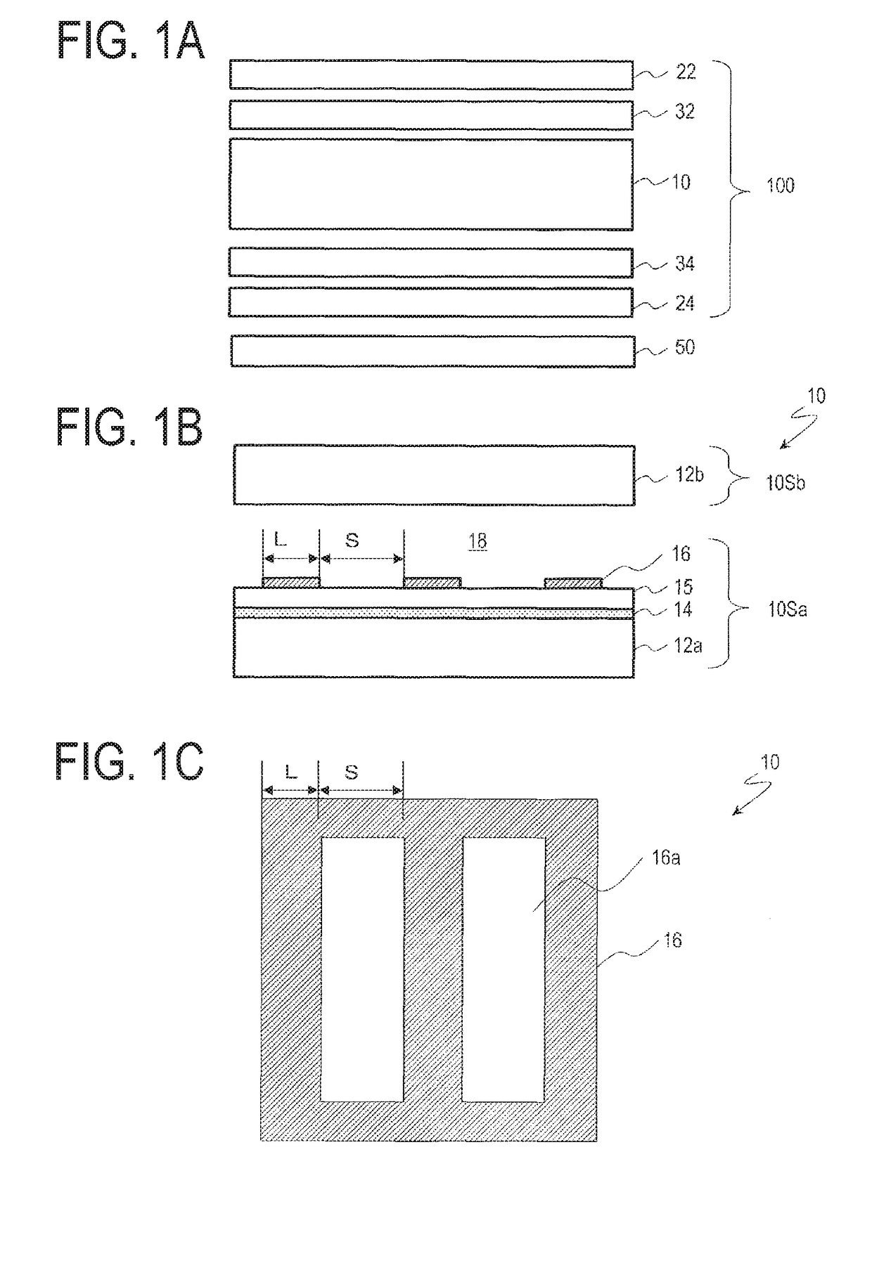
[0154]A configuration of a liquid crystal display panel 100 according to the first embodiment of the present invention will be described with reference to FIG. 1. FIG. 1A is a schematic exploded cross-sectional view of the liquid crystal display panel 100 according to a first embodiment of the present invention, also illustrating a backlight 50; FIG. 1B is a schematic cross-section of a part corresponding to a single pixel in a liquid crystal cell 10 included in the liquid crystal display panel 100; and FIG. 1C is a schematic plan view of a part corresponding to a single pixel in the liquid crystal cell 10.

[0155]As illustrated in FIG. 1A, the liquid crystal display panel 100 includes: the liquid crystal cell 10; a first polarizing plate 22 disposed on an observer side of the liquid crystal cell 10; a first phase difference plate 32 disposed between the liquid crystal cell 10 and the first polarizing plate 22; a second polarizing plate 24 disposed on a back surface side of the liquid...

second embodiment

[0241]A structure of a liquid crystal display panel according to a second embodiment of the present invention will be described below with reference to FIGS. 30A-A to 30C-B. FIG. 30A-A is a schematic exploded cross-sectional view of a liquid crystal display panel 100A according to the second embodiment of the present invention, and FIG. 30A-B is a schematic exploded cross-sectional view of a liquid crystal display panel 100B according to the second embodiment of the present invention. FIG. 30B-A is a schematic exploded cross-sectional view of a liquid crystal display panel 100B1 according to the second embodiment of the present invention; FIG. 30B-B is a schematic exploded cross-sectional view of a liquid crystal display panel 100B2 according to the second embodiment of the present invention; and FIG. 30B-C is a schematic exploded cross-sectional view of a liquid crystal display panel 100B3 according to the second embodiment of the present invention. FIG. 30C-A is a schematic explod...


PUM

PropertyMeasurementUnit
thicknessaaaaaaaaaa
widthaaaaaaaaaa
angleaaaaaaaaaa

Abstract

A liquid crystal display panel (100A) includes a first polarizing plate (22) and a first phase difference plate (32a) disposed on an observer side, and a second polarizing plate (24) and a second phase difference plate (34a) disposed on a back surface side. Δnd of a liquid crystal layer having a homogeneous alignment when no electrical field is applied is 360 nm or greater and 490 nm or less, and an in-plane retardation R1 of the first phase difference plate is 100 nm or greater and 160 nm or less. A thickness direction retardation of at least one of the first and second phase difference plates has a negative value. The slow axes of the first and second phase difference plates are substantially parallel to each other and substantially orthogonal to an azimuthal direction of the liquid crystal director.

Description

TECHNICAL FIELD[0001]The present invention relates to a liquid crystal display panel, and particularly relates to a liquid crystal display panel having a transverse electrical field mode.BACKGROUND ART[0002]Liquid crystal display panels having a transverse electrical field mode, such as an In-Plane Switching (IPS) mode or a Fringe Field Switching (FFS) mode, have an advantage over known liquid crystal display panels having vertical electrical field mode (VA mode, for example) in that the viewing angle dependence of γ (gamma) properties is low. Hence, the use of such panels as small- and medium-sized liquid crystal display panels in particular is increasing.[0003]However, as the resolutions of liquid crystal display panels increase, the pixel aperture ratios (a ratio of the total surface area of the pixel openings occupying the display region) decrease, and it is becoming difficult to achieve a satisfactory display luminance. Particularly in small- and medium-sized liquid crystal dis...

Claims


Application Information

Patent Timeline
Patent Type & Authority Applications(United States)
IPC IPC(8): G02F1/13363G02F1/1337G02F1/1335
CPCG02F1/133634G02F1/1337G02F1/133528G02F2001/133567G02F2001/133562G02F2001/133738G02F2413/04G02F2413/06G02F2413/12G02F2413/11G02F2413/13G02F2001/133541G02F1/134363G02B5/3083G02F1/13363G02F2413/02G02F2413/05G02F2413/14G02F1/133638G02F1/133738G02F1/133541G02F1/133562G02F1/133567
Inventor SAKAI, AKIRANAKAMURA, KOHZOHHASEGAWA, MASAHIROKOIDE, TAKAKOMINOURA, KIYOSHI
Owner SHARP KK
Why Eureka
Try Eureka