Liquid crystal cell and liquid crystal display apparatus

a liquid crystal cell and liquid crystal display technology, applied in the field of liquid crystal cells and liquid crystal displays, can solve the problems of increasing thickness by the use of plural films, lowering the production yield of adhering plural films, and increasing production costs, so as to improve color reproducibility in a white state, the effect of high contrast and decreasing the change of contras

Inactive Publication Date: 2009-08-27
FUJIFILM CORP
View PDF6 Cites 3 Cited by
  • Summary
  • Abstract
  • Description
  • Claims
  • Application Information

AI Technical Summary

Benefits of technology

[0006]An object of the present invention is to provide a liquid crystal display apparatus, particularly a VA-mode liquid crystal display apparatus, in which a liquid crystal cell is exactly compensated optically, thereby providing a high contrast. In particular, an object of the present invention is to provide a liquid crystal display apparatus and liquid crystal cell of VA mode, which are improved in the color reproducibility in a white state when viewed at an oblique angle, are decreased in the contrast change depending on a viewing angle, and are reduced in the peripheral part of the image displaying area.
[0023]According to the present invention, by disposing a multi-domain optical compensation film, which is formed through suitable selection of materials and a producing method, between a pair of substrates of a liquid crystal cell, it is possible to provide a liquid crystal apparatus which is improved in a transmittance loss due to multiple reflection and in a luminance or a contrast ratio. And it is also possible to improve the color reproducibility in a white state and to reduce the viewing angle dependence of the luminance by optically compensating the retardation of the liquid crystal layer with the multi-domain optical compensation film in which an aligning direction in each domain is different in planar or in thickness direction, or in which a retardation in each domain is different in planar or thickness direction.

Problems solved by technology

845-848) not only results in an increased production cost but also leads to drawbacks of a lowered production yield in adhering plural films and an increased thickness by the use of plural films, unfavorable for a thickness reduction of the display apparatus.
Also an adhesion layer disposed between the oriented films may show a contraction by changes in temperature and humidity, thus resulting in defects such as a peeling or a bending of the films, or particularly an un-uniformity in the image display in a peripheral portion of the display panel.
However, these methods, though effective for the viewing angle property in the black state, cannot completely solve a drawback of deterioration in the color reproduction (color washout, or a saturation loss in displayed color) in a white state when viewed under an oblique angle.

Method used


Image

  • Liquid crystal cell and liquid crystal display apparatus
  • Liquid crystal cell and liquid crystal display apparatus
  • Liquid crystal cell and liquid crystal display apparatus

Examples


example 1

[0192]Two cell samples were prepared with glass substrates with electrodes of a size of 30×40 mm, and subjected to measurements of optical characteristics.

[0193]To a surface of the glass substrate, a coating liquid of a following composition was applied by a #16 wire bar coater with an amount of 28 mL / m2, and dried for 60 seconds with warm air of 60° C. and for 150 seconds with warm air of 90° C. Then the formed film was subjected to a rubbing process for obtaining an alignment parallel to an in-plane slow axis (parallel to casting direction) of the cellulose acetate film (thus the rubbing axis being parallel to the in-plane slow axis of cellulose acetate film).

Composition of a coating liquid for forming an20parts by massalignment film following denatured polyvinylalcoholWater360parts by massMethanol120parts by massGlutaraldehyde (crosslinking agent)1.0part by massdenatured polyvinyl alcohol

[0194]To a surface of the alignment film, a coating liquid prepared by dissolving 91.0 g of a...

example 2

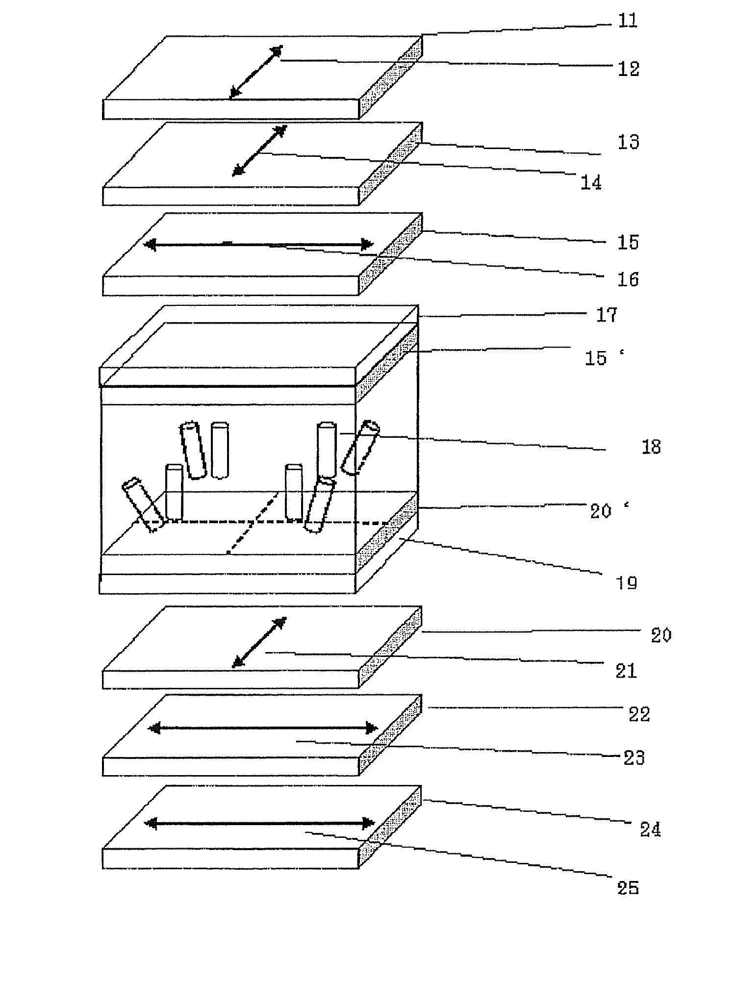
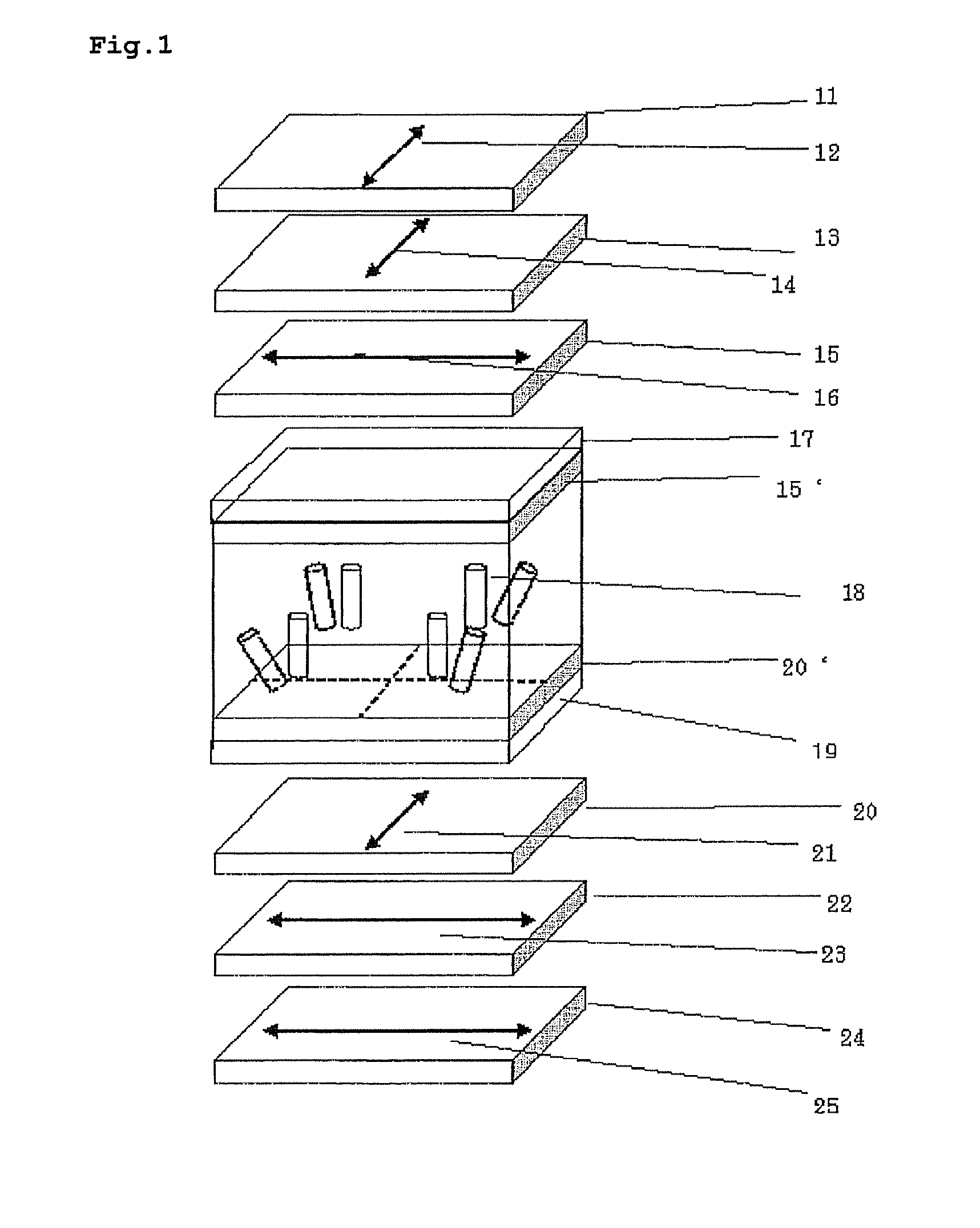
[0199]An optical simulation was conducted for confirming the effect, on an assumed liquid crystal display apparatus of a structure similar to that shown in FIGS. 1 and 8, constituted by laminating, from the observing (upper) side, an upper polarizing plate (protective film 11, polarizing film 13, and protective film 15 (also serving as an optical compensation film)), a liquid crystal cell (upper substrate 17, liquid crystal layer 18 and lower substrate 19), and a lower polarizing plate (protective film 20 (also serving as an external optical compensation film), polarizing film 22 and protective film 24), and positioning a backlight source (not shown) thereunder. The optical calculation was carried out with LCD Master Cer. 6.08 of Syntech Inc. For the liquid crystal cell, substrates and polarizing plates, values of the materials commonly employed in the liquid crystal display were employed. The liquid crystal material was assumed to have a negative dielectric anisotropy with Δ∈=−4.2....

example 3

[0204]In the liquid crystal cell of Example 1, an optical compensation layer was formed of a rod-like liquid crystal composition on the glass substrate, with an alignment direction parallel to a surface of the substrate and forming a crossing angle of 45° with the absorption axis 14 of the upper polarizing film 13. It was given a thickness of 1.8 μm and Re of 140 nm at a wavelength of 550 nm. Rth was 70 nm. It was photopolymerized by a UV irradiation by shielding a half area of the substrate from light, and the compensation film in an unpolymerized part was then removed by rinsing with isopropyl alcohol.

[0205]Under the liquid crystal cell, a white aluminum reflective film was provided in a portion corresponding to where the optical compensation film was formed, and a polarizing plate, with an absorption axis parallel to that of the upper polarizing plate, was provided in a portion corresponding to where the optical compensation film was removed.

[0206]In the visual observation of the...


PUM


Abstract

A novel liquid crystal display apparatus is disclosed. The apparatus comprises a liquid crystal cell comprising a pair of substrates which are provided in mutually opposed manner and which has an electrode in at least either thereof, and a liquid crystal material supported between the pair of substrates; a first polarizing film disposed outside the liquid crystal cell; and at least an in-cell optical compensation film disposed between the pair of substrates, with plural domains per a pixel having a different mean alignment direction each other.

Description

TECHNICAL FIELD[0001]The present invention relates to a liquid crystal cell and a liquid crystal display improved in viewing angle property.RELATED ART[0002]A liquid crystal display device usually comprises a liquid crystal cell and polarizing plates. The polarizing plate usually has protective films and a polarizing film, and is obtained typically by dying the polarizing film composed of a polyvinyl alcohol film with iodine, stretching, and being stacked on both surfaces thereof with the protective films. A transmissive liquid crystal display device usually comprises polarizing plates on both sides of the liquid crystal cell, and occasionally comprises one or more optical compensation films. A reflective liquid crystal display device usually comprises a reflector plate, the liquid crystal cell, one or more optical compensation films, and a polarizing plate in this order. The liquid crystal cell comprises liquid-crystalline molecules, two substrates encapsulating the liquid-crystall...

Claims


Application Information

Patent Timeline
Patent Type & Authority Applications(United States)
IPC IPC(8): G02F1/1347G02F1/1335
CPCG02B5/3016G02F1/133634G02F2413/105G02F1/1393G02F1/133753G02B5/30G02F1/1335G02F1/13363
Inventor HIRAKATA, JUNICHI
Owner FUJIFILM CORP
Why Eureka
Try Eureka