Apparatus and method for generating a frequency enhancement signal using an energy limitation operation

a technology of energy limitation and frequency enhancement, applied in the field of audio coding, can solve the problems of not being acceptable for a given application scenario, difficult to generate artificial signals, and most listeners perceive the missing highpass part as a quality degradation, so as to avoid the continuation of small fast energy fluctuations, enhance the frequency range, and improve the effect of quality

Active Publication Date: 2015-11-19
FRAUNHOFER GESELLSCHAFT ZUR FOERDERUNG DER ANGEWANDTEN FORSCHUNG EV
View PDF13 Cites 9 Cited by
  • Summary
  • Abstract
  • Description
  • Claims
  • Application Information

AI Technical Summary

Benefits of technology

[0032]In a further aspect, a temporal smoothing procedure is applied. A signal generator for generating an enhancement signal from a core signal is provided. A time portion of the enhancement signal or the core signal comprises subband signals for a plurality of subbands. A controller for calculating the same smoothing information for the plurality of subband signals of the enhancement frequency range is provided and this smoothing information is then used by the signal generator for smoothing the plurality of subband signals of the enhancement frequency range, particularly using the same smoothing information or, alternatively, when the smoothing is performed before the high frequency generation, then the plurality of subband signals of the core signal are smoothed all using the same smoothing information. This temporal smoothing avoids the continuation of smaller fast energy fluctuations, which are inherited from the low-band, to the high-band, and thus leads to a more pleasant perceptual impression. The low-band energy fluctuations are usually caused by quantization errors of the underlying core-coder that lead to instabilities. The smoothing is signal adaptive since it is dependent on the (long-term) stationary of the signal. Furthermore, the usage of one and the same smoothing information for all individual subbands makes sure that the coherency between the subbands is not changed by the temporal smoothing. Instead, all subbands are smoothed in the same way, and the smoothing information is derived from all subbands or from only the subbands in the enhancement frequency range. Thus, a significantly better audio quality compared to an individual smoothing of each subband signal individually is obtained.

Problems solved by technology

Although this approach guarantees an acceptable quality for the coded low-frequency signal, most listeners perceive the missing of the highpass part as a quality degradation.
If this frequency is close to the crossover frequency, then it can be problematic to generate the artificial signal above the crossover frequency since in that case the lowband does contain little relevant signal parts.
However, this necessitates additional bitrate, which might not be acceptable for a given application scenario.
This creates audible artifacts if the HF signal is combined with a tonal, harmonic low-frequency signal (e.g. music).
To avoid such artifacts, G.722.2 strongly limits the energy of the generated HF signal, which also limits potential benefits of the bandwidth extension.
Thus, unfortunately also the maximum possible improvement of the brightness of a sound or the maximum obtainable increase in intelligibility of a speech signal is limited.2. Since this non-guided bandwidth extension operates in the time domain, the filter operations cause additional algorithmic delay.
This additional delay lowers the quality of the user experience in bi-directional communication scenarios or might not be allowed by the terms of requirement of a given communication technology standard.3. Also, since the signal processing is performed in time domain, the filter operations are prone to instabilities.
Moreover, the time domain filters have a high computational complexity.4. Since only the overall sum of the energy of the high band signal is adapted to the energy of the core signal (and further weighted by the spectral tilt), there might be a significant local mismatch of energy at the crossover frequency between upper frequency range of the core signal (the signal just below the crossover frequency) and the high band signal.
For example, this will be the case especially for tonal signals that exhibit an energy concentration in the very low frequency range but contain little energy in the upper frequency range.5. Furthermore, it is computationally complex to estimate a spectral slope in a time domain representation.
To summarize, the conventional non-guided or blind bandwidth extension schemes may necessitate a significant computational complexity on the decoder side and nevertheless result in a limited audio quality specifically for problematic speech sounds such as fricatives.
Furthermore, guided bandwidth extension schemes, although providing a better audio quality and sometimes necessitating less computational complexity on the decoder side cannot provide the substantial bitrate reductions due to the fact that the additional parametric information on the high band can necessitate a significant amount of additional bitrate with respect to the encoded core audio signal.
Furthermore it is computationally complex to precisely estimate and extrapolate a given spectral shape in the time domain.
In the time domain, it is difficult to detect this situation and computationally complex to obtain a valid extrapolation from it.
The low-band energy fluctuations are usually caused by quantization errors of the underlying core-coder that lead to instabilities.
This procedure is particularly useful for non-guided bandwidth extension schemes, but can also help in guided bandwidth extension schemes, since the non-guided bandwidth extension schemes are prone to artifacts caused by spectral components which stick out unnaturally, especially at segments which have a negative spectral tilt.
These components might lead to high-frequency noise-bursts.

Method used


Image

  • Apparatus and method for generating a frequency enhancement signal using an energy limitation operation
  • Apparatus and method for generating a frequency enhancement signal using an energy limitation operation
  • Apparatus and method for generating a frequency enhancement signal using an energy limitation operation

Examples


Embodiment Construction

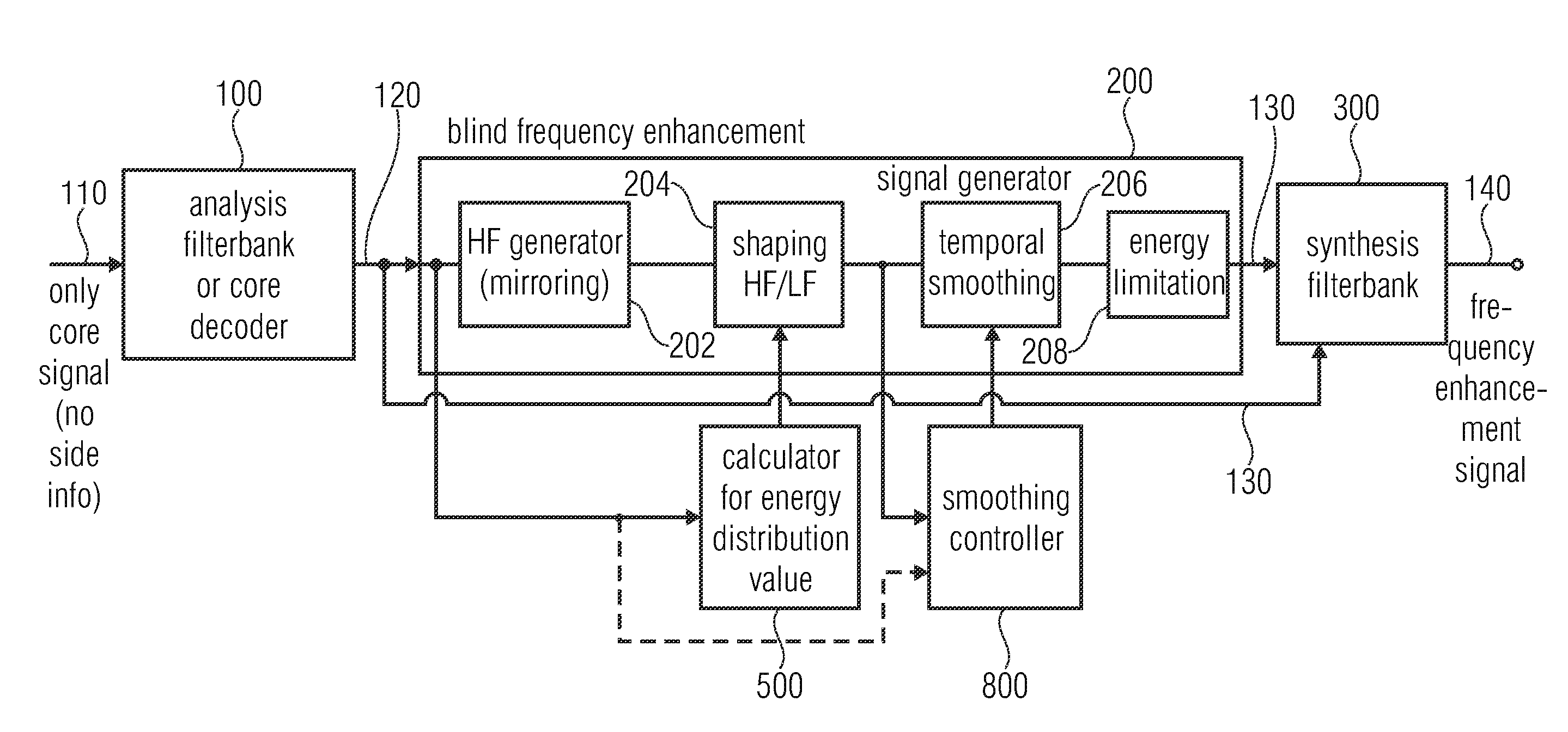
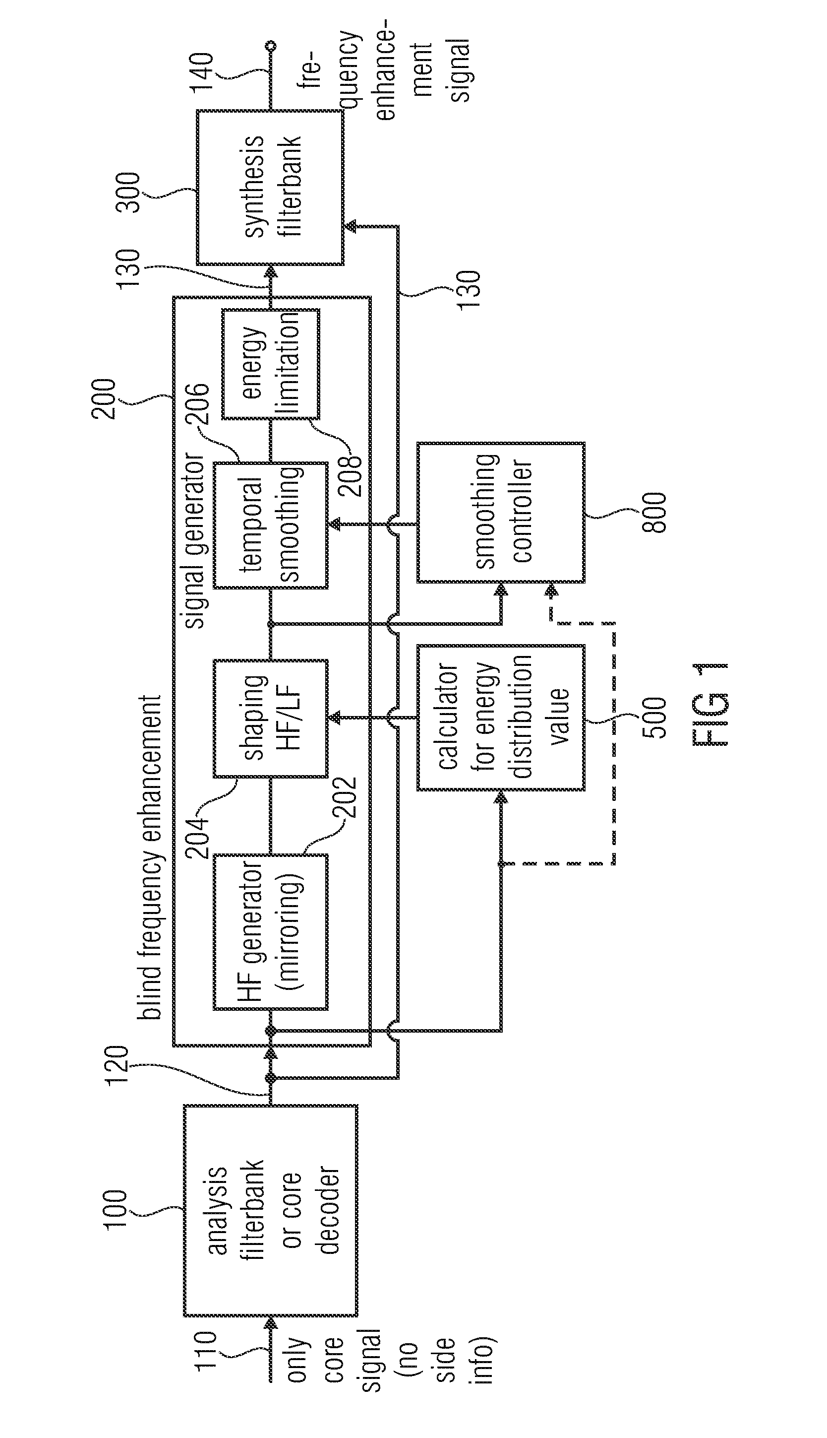
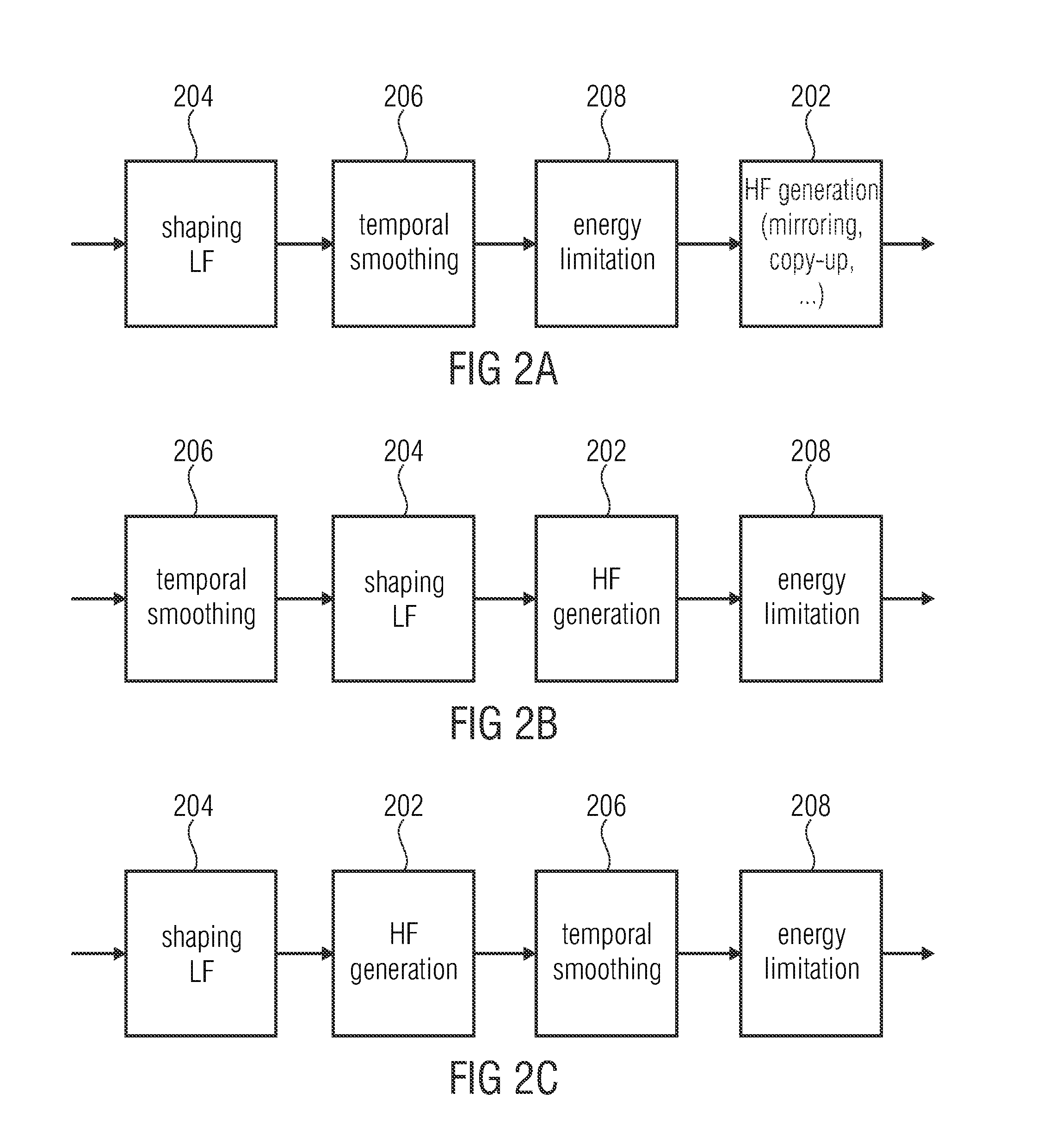
[0053]FIG. 1 illustrates an apparatus for generating a frequency enhanced signal 140 in an implementation, in which the technologies of shaping, temporal smoothing and energy limitation are performed all together. However, these technologies can also be individually applied as discussed in the context of FIGS. 5 to 7 for the shaping technology, FIGS. 8 to 10 for the smoothing technology and FIGS. 11 to 13 for the energy limitation technology.

[0054]The apparatus for generating the frequency enhanced signal 140 of FIG. 1 comprises an analysis filterbank or a core decoder 100 or any other device for providing the core signal in the filterbank domain such as in a QMF domain, when the core decoder outputs QMF subband signals. Alternatively, the analysis filterbank 100 can be a QMF filterbank or another analysis filterbank, when the core signal is a time domain signal or is provided in any other domain than a spectral or subband domain.

[0055]The individual subband signals of the core sign...


PUM


Abstract

An apparatus for generating a frequency enhancement signal, includes: a signal generator for generating an enhancement signal from a core signal, the enhancement signal including an enhancement frequency range not included in the core signal, wherein a time portion of the enhancement signal includes subband signals for a plurality of subbands; a synthesis filterbank for generating the frequency enhanced signal using the enhancement signal, wherein the signal generator is configured for performing an energy limitation in order to make sure that the frequency enhanced signal obtained by the synthesis filterbank is so that an energy of a higher band is, at the most, equal to an energy in a lower band or is greater than an energy of a higher band, at the most, by a predefined threshold.

Description

CROSS-REFERENCE TO RELATED APPLICATIONS [0001]This application is a continuation of copending International Application No. PCT / EP2014 / 051603, filed Jan. 28, 2014, which claims priority from U.S. Application No. 61 / 758,090, filed Jan. 29, 2013, which are each incorporated herein in its entirety by this reference thereto.BACKGROUND OF THE INVENTION [0002]The present invention is based on audio coding and in particular on frequency enhancement procedures such as bandwidth extension, spectral band replication or intelligent gap filling.[0003]The present invention is particularly related to non-guided frequency enhancement procedures, i.e. where the decoder-side operates without side information or only with a minimum amount of side information.[0004]Perceptual audio codecs often quantize and code only a lowpass part of the whole perceivable frequency range of an audio signal, especially when operated at (relatively) low bitrates. Although this approach guarantees an acceptable quality ...

Claims


Application Information

Patent Timeline
Patent Type & Authority Applications(United States)
IPC IPC(8): G10L21/0388G10L19/12G10L19/032
CPCG10L21/0388G10L2019/0016G10L19/12G10L19/032G10L21/038G10L19/0204G10L25/18G10L2019/0012G10L19/06
Inventor DISCH, SASCHAGEIGER, RALFHELMRICH, CHRISTIANMULTRUS, MARKUSSCHMIDT, KONSTANTIN
Owner FRAUNHOFER GESELLSCHAFT ZUR FOERDERUNG DER ANGEWANDTEN FORSCHUNG EV
Why Eureka
Try Eureka