Work vehicle and control method for same

a technology for working vehicles and control methods, applied in the field of work vehicles, can solve the problems of difficult to realize the shuttle action in a work vehicle provided with hmt or emt, difficult to absorb the difference in rotation speed between the r-clutch connection time, and excessive friction between the r-clutch and the f-clutch, etc., to achieve the effect of improving the operability of the wheel loader

Active Publication Date: 2015-11-26
KOMATSU LTD
View PDF4 Cites 10 Cited by
  • Summary
  • Abstract
  • Description
  • Claims
  • Application Information

AI Technical Summary

Benefits of technology

[0008]With the conventional torque converter-type transmission device, when the operator performs a switching operation of the vehicle moving forward from forward travel to reverse travel, the forward travel clutch (referred to below as “F-clutch”) is promptly disconnected and the connection of the reverse travel clutch (referred to below as “R-clutch”) is started. As a result, the vehicle decelerates smoothly and then begins to accelerate in the reverse direction. Similarly, when the operator performs a switching operation of the vehicle moving in reverse from reverse travel to forward travel, the R-clutch is promptly disconnected and the connection of the F-clutch is started. As a result, the vehicle decelerates smoothly and then accelerates in the forward direction. In general, the switching operation between forward and reverse travel while traveling is called a shuttle operation and the action of the vehicle due to the shuttle operation is called a shuttle action. The shuttle action is one of the important functions for improving operability of a wheel loader.
[0016]The work vehicle is preferably further provided with an accelerator operating member, an accelerator operation detecting unit for detecting an operating amount of the accelerator operating member, a brake operating member, and a brake operation detecting unit for detecting an operating amount of the brake operating member. The target output shaft torque determination unit determines a predetermined reference deceleration force on the basis of the operating amount of the accelerator operating member and the operating amount of the brake operating member. The target output shaft torque determination unit gradually changes the deceleration force approaching the reference deceleration force during the shuttle action. In this case, operability can be improved because a deceleration force that takes into account the operating desire of the operator can be generated.
[0019]When a torque for accelerating the vehicle is generated in the output shaft of the power transmission device when the shuttle action starts, the target output shaft torque determination unit preferably determines the target output shaft torque so that the torque on the output shaft of the power transmission device changes to zero in a predetermined first time period. The target output shaft torque determination unit changes the deceleration force approaching the reference deceleration force in a second time period that is longer than the first time period after the first time period has elapsed. In this case, the work vehicle can be decelerated quickly and smoothly after the start of the shuttle action.
[0021]The work vehicle preferably is further provided with an energy reservoir unit for storing energy generated in the motor. The control unit further has a target energy reservoir power determination unit. The target energy reservoir power determination unit determines a target energy reservoir power for accumulating energy in the energy reservoir unit. The target output shaft torque determination unit calculates the deceleration power regenerated by the deceleration force. The target input shaft torque determination unit determines the target input shaft torque on the basis of the target energy reservoir power and the deceleration power. In this case, a desired deceleration force can be ensured and a desired energy reservoir amount can be ensured when the target input shaft torque is determined by taking into account the regenerated deceleration power and the target energy reservoir power, and consequently fuel consumption can be improved.

Problems solved by technology

However, it is difficult to absorb the difference in rotation speed between the R-clutch connection time and the F-clutch connection during the shuttle action due to the mechanism in the above mentioned HMT or EMT.
When the switching of the R-clutch and the F-clutch is implemented during the shuttle action in the HMT or the EMT and when a large load is applied to the engine at the same time, there is a concern that excessive friction may occur in the R-clutch and the F-clutch.
Therefore, it is difficult to realize the shuttle action in a work vehicle provided with a HMT or an EMT.

Method used


Image

  • Work vehicle and control method for same
  • Work vehicle and control method for same
  • Work vehicle and control method for same

Examples


Embodiment Construction

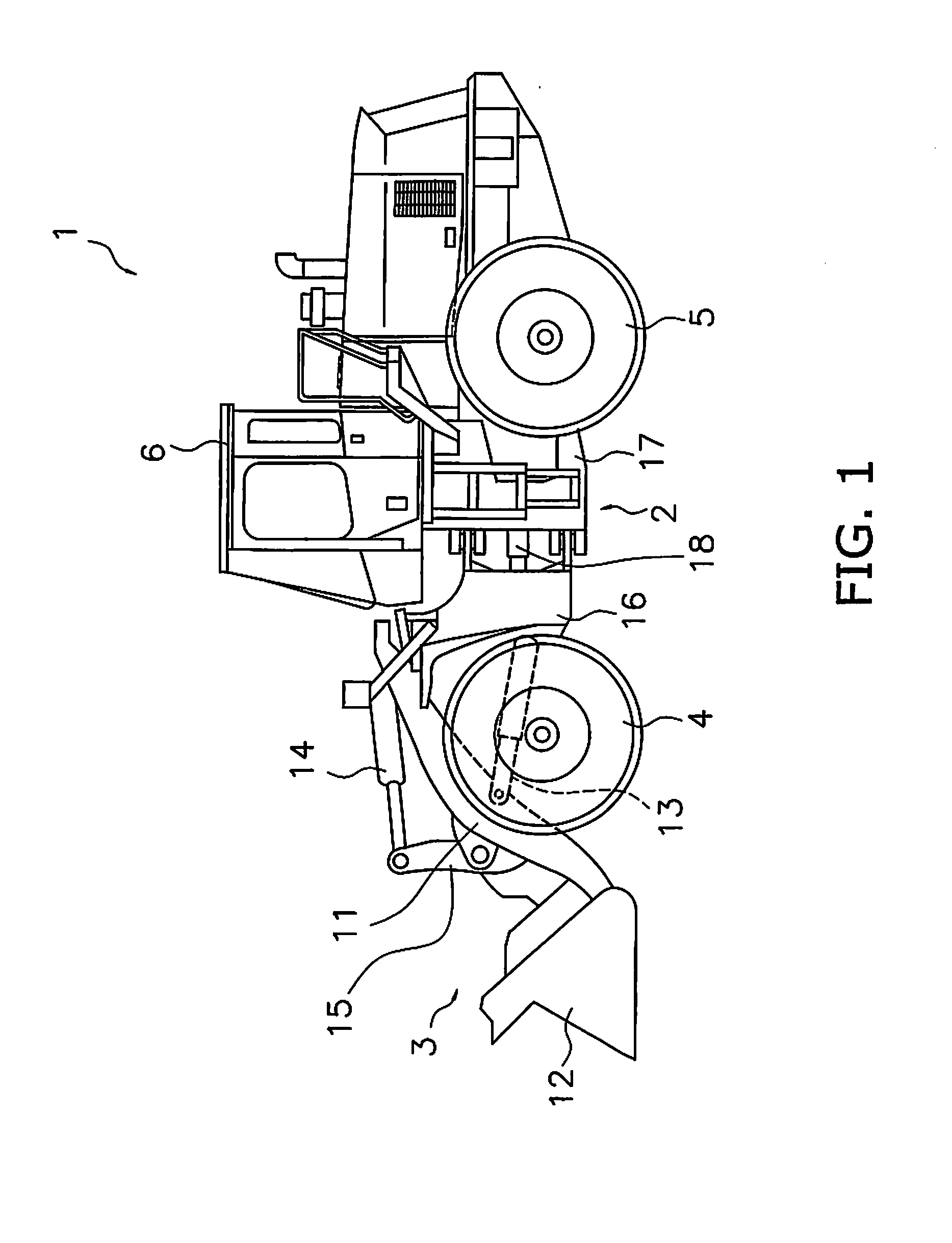
[0040]Exemplary embodiments of the present invention will be explained in detail with reference to the figures. FIG. 1 is a side view of a work vehicle 1 according to an exemplary embodiment of the present invention. As illustrated in FIG. 1, the work vehicle 1 is equipped with a vehicle body frame 2, a work implement 3, traveling wheels 4 and 5, and an operating cabin 6. The work vehicle 1 is a wheel loader and travels due to the traveling wheels 4 and 5 being rotated and driven. The work vehicle 1 is able to carry out work, such as excavation, by using the work implement 3.

[0041]The work implement 3 and the traveling wheels 4 and 5 are attached to the vehicle body frame 2. The work implement 3 is driven by hydraulic fluid from a below mentioned work implement pump 23 (see FIG. 2). The work implement 3 has a boom 11 and a bucket 12. The boom 11 is mounted on the vehicle body frame 2. The work implement 3 includes a lift cylinder 13 and a bucket cylinder 14. The lift cylinder 13 and...


PUM


Abstract

The target input shaft torque determination unit determines a target input shaft torque. The target output shaft torque determination unit determines a target output shaft torque so that a deceleration force for decelerating the vehicle is generated on the output shaft of the power transmission device in a state in which connection and disconnection states of the forward travel clutch and the reverse travel clutch are maintained at the state before the start of the shuttle action when the shuttle action is started. The torque-balance information is stored in a storage unit and defines a relationship between the target input shaft torque and the target output shaft torque to achieve a balance of the torques of a power transmission device. The command torque determination unit uses the torque-balance information to determine torque commands for the motor from the target input shaft torque and the target output shaft torque.

Description

CROSS-REFERENCE TO RELATED APPLICATIONS[0001]This application is a U.S. National stage application of International Application No. PCT / JP2014 / 073187, filed on Sep. 3, 2014. This U.S. National stage application claims priority under 35 U.S.C. §119(a) to Japanese Patent Application No. 2013-217412, filed in Japan on Oct. 18, 2013, the entire contents of which are hereby incorporated herein by reference.BACKGROUND[0002]1. Field of the Invention[0003]The present invention relates to a work vehicle and a control method for the work vehicle.[0004]2. Background Information[0005]An invention provided with a power transmission device (referred to hereinbelow as a “torque converter-type transmission device”) having a torque converter and a multi-stage speed change gear is well known as a work vehicle, such as a wheel loader. However, recently hydraulic mechanical transmissions (HMT) have become known as power transmission devices in place of torque converter-type transmissions. As disclosed ...

Claims


Application Information

Patent Timeline
Patent Type & Authority Applications(United States)
IPC IPC(8): F15B21/00F15B1/02B60L50/16
CPCF15B21/001F15B2201/00F15B1/02B60K6/445B60W10/08B60W10/10B60W10/26B60W20/00B60L50/16B60L50/50F16H3/66F16H3/72B60K6/12B60K6/365B60K6/387B60K6/547B60K2006/381B60L7/18B60L2200/40B60L2240/12B60L2240/421B60L2260/26B60W10/06B60W10/115B60W20/10B60W30/18045B60W2300/17B60W2710/0666B60W2710/083B60L58/12E02F9/202E02F9/2079F16H3/728F16H2037/101F16H2200/2007F16H2200/2041Y02T10/62Y02T10/64Y02T10/70
Inventor MIYAMOTO, SHUNSUKEYAMADA, KENICHIOHKURA, YASUNORIKISHIMOTO, YASUKIYOSHIZAWA, MASAO
Owner KOMATSU LTD
Why Eureka
Try Eureka