Cam follower with Anti-rotation device

a technology of anti-rotation and follower, which is applied in the direction of positive displacement liquid engine, piston pump, machine/engine, etc., can solve the problems of damage to the device using the plunger, and achieve the effect of improving sliding

Active Publication Date: 2015-11-26
AB SKF
View PDF3 Cites 7 Cited by
  • Summary
  • Abstract
  • Description
  • Claims
  • Application Information

AI Technical Summary

Benefits of technology

[0015]Moreover, the projecting end of the sleeve may have a profile different from that of the main part of the sleeve. The end of the sleeve may have a non-circular profile, for example a rectangular or elliptical profile to improve sliding in the matching groove, prevent axial movements in the direction opposite to that of the projecting end and prevent rotation of the sleeve about its longitudinal axis, if required. Furthermore, the invention proposes to provide the sleeve with a bolt head constituting said anti-rotation device for any of the abovementioned purposes.

Problems solved by technology

Moreover, there is a risk of the element loosening, which can damage the device using the plunger.

Method used


Image

  • Cam follower with Anti-rotation device
  • Cam follower with Anti-rotation device
  • Cam follower with Anti-rotation device

Examples


second embodiment

[0033]FIG. 5 shows the invention characterized in that the sleeve 16 is fixed inside the plunger body 12 by a circlip 20. The position of the sleeve 16 is fixed so that the axial ends do not come into contact with the walls or the bottom of the matching structure or the groove, which makes it possible to avoid machining the ends to round them or coating them.

[0034]The circlip 20 is fixed to the end 16a of the sleeve 16 positioned on the exterior wall of said plunger body 12 directly adjoining the wall of the plunger body 12. The circlip 20 engages in a circumferential groove (not shown) in the exterior surface of the sleeve 16. The sleeve 16 features a central bore that reduces its weight and simplifies handling it when the axial ends are machined or coated.

third embodiment

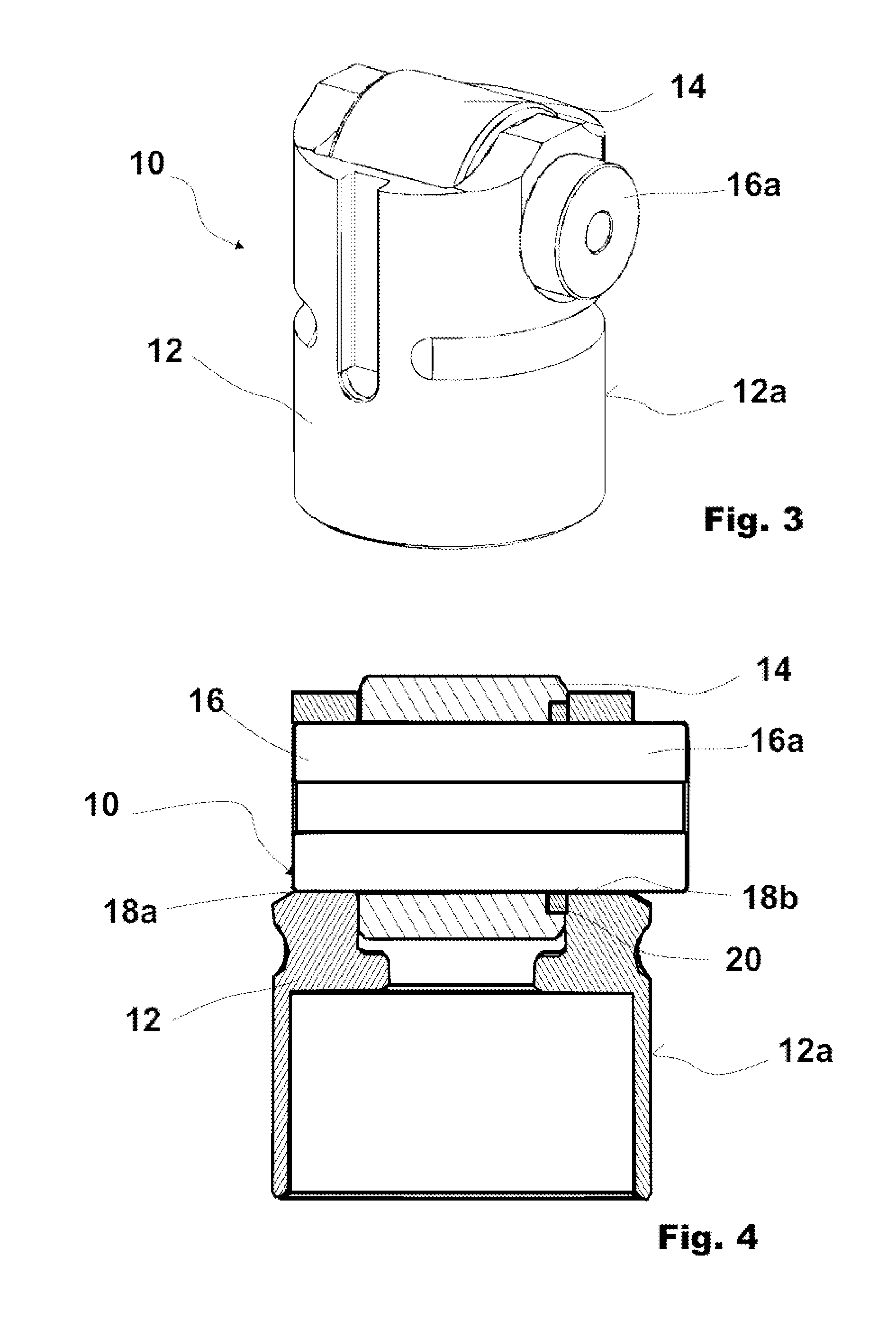
[0035]FIG. 4 shows the invention characterized in that a circlip 20 is fixed to the sleeve 16 positioned on the interior wall of said plunger body 12 and in particular between the roller 14 and the interior wall of the plunger body 12, the axial end of the roller 14 including a groove adapted to receive the circlip 20. The circlip 20 engages in a circumferential groove 22 on the exterior surface of the sleeve 16.

[0036]Another economical way to fix the axial position of the sleeve 16 inside the plunger body 12 is by a plastic deformation 22 of the sleeve 16 of rod shape, for example by bossing up. FIG. 6 is a diagrammatic representation of this. The plastic deformation 22 of the sleeve is on an axially intermediate portion of the exterior surface 22a of the sleeve so that the sleeve has a shaft end portion 22b constituting all or part of the anti-rotation device. The plastic deformation advantageously extends all around the circumference of the exterior surface 22a of the sleeve. In ...


PUM


Abstract

A cam follower including a plunger intended to execute a reciprocating movement in an exterior body. The plunger includes a plunger body having a cylindrical exterior surface, an anti-rotation device extending radially beyond the cylindrical exterior surface of the pusher body and engaging via a matching structure in the exterior body, a roller providing the contact with a cam, and a sleeve rotatably supporting the roller in the plunger body. The plunger body includes at least one lateral bore and the sleeve is inserted in the bore. In order to avoid additional components and assembly steps to constitute the anti-rotation device, the present invention proposes to use one end of the sleeve as the anti-rotation device.

Description

CROSS REFERENCE TO RELATED APPLICATIONS[0001]This is a United States National Stage Application claiming the benefit of International Application Number PCT / EP2013 / 075143 filed on 29 Nov. 2013 (29.11.2013), which claims priority to France Patent Application 12 / 03228 filed on 29 Nov. 2012 (29.11.2012), which are incorporated herein by reference in their entireties.FIELD OF THE INVENTION[0002]The present invention concerns cam followers including a plunger with a roller providing the contact with a cam. Cam followers of this type are used in particular for fuel injection pumps, valve control and other similar systems in automotive applications. The invention is not applicable only to cam followers. Another application of the invention concerns the use of the device for other reciprocating elements including a sleeve disposed in a direction transverse to the direction of the reciprocating movement.[0003]Prior ArtIn the field of cam followers, it is particularly important to ensure that...

Claims


Application Information

Patent Timeline
Patent Type & Authority Applications(United States)
IPC IPC(8): F16H53/06F01L1/14F02M59/10
CPCF16H53/06Y10T74/2107F01L1/14F02M59/102F04B1/0439F04B9/042F01L2305/02F01L2307/00
Inventor VAN DER MEI, NIJSHAUVESPRE, BENO T
Owner AB SKF
Why Eureka
Try Eureka